


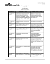

10.6 Checking
LED MODULE
WARNING
Failure to turn off power to the sign and wait five minutes could result
in severe injury or dea
Turn off power to the sign by turning off the corresponding Constant Current Regulator (CCR) power.
(WARNING: W
ait five minutes after sign power is turned off
any residual high voltage
stored in Power Supply
multimeter set to DC Volts, verify that the Power Supply Output Voltage is less than 30
(Positive lead) and TP3 (Negative Lead) as indicated in Figure 22. If the Power Supply Output Voltage
is greater than 30-
VDC, then you must wait until the Power Supply Output Voltage drops below 30
before you proceed with the next step.
The LED MODULES
are electrically wired in series. This means that if
improperly seated in their re
spective
the LED MODULES
and subsequently the sign will not light. Therefore, verify that all cable connectors
are properly seated in their housing and that the output of one
pointing arrow at the
LED MODULE
MODULE
(indicated by the inward pointing arrow at the
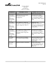
The Last LED MODULE
in the series string is terminated
assembly(See Figure 7-11).
Verify that
connector housing at the Last
LED MODULE
10.7 Checking the First
LED MODULE
WARNING
Failure to turn off power to the sign and wait five minutes could result
in severe injury or death.
Instruction Manual
AGS-LED
858 LED Series
Sizes 1, 2, 3, 4 and 5
12
LED MODULE
Cable Connections
WARNING:
Failure to turn off power to the sign and wait five minutes could result
in severe injury or dea
th.
Turn off power to the sign by turning off the corresponding Constant Current Regulator (CCR) power.
ait five minutes after sign power is turned off
to service the sign
. This will allow
stored in Power Supply
PCB components to bleed off
.) With your
multimeter set to DC Volts, verify that the Power Supply Output Voltage is less than 30
(Positive lead) and TP3 (Negative Lead) as indicated in Figure 22. If the Power Supply Output Voltage
VDC, then you must wait until the Power Supply Output Voltage drops below 30
before you proceed with the next step.
are electrically wired in series. This means that if
any
of the cable connectors are
spective
LED MODULE
housing, then no current can flow through
and subsequently the sign will not light. Therefore, verify that all cable connectors
are properly seated in their housing and that the output of one
LED MODULE
(indicate
LED MODULE
connector Figure 7
) is connected to the input of the next
(indicated by the inward pointing arrow at the
LED MODULE connector-
Figure 7
in the series string is terminated
with a black
return connector & cable
Verify that
the black terminator cable connector
is properly inserted into the
LED MODULE
output connector (indicated by the in
ward pointing arrow).
LED MODULE
WARNING:
Failure to turn off power to the sign and wait five minutes could result
in severe injury or death.
DOCUMENT 1025
REV. B
Failure to turn off power to the sign and wait five minutes could result
Turn off power to the sign by turning off the corresponding Constant Current Regulator (CCR) power.
. This will allow
.) With your
multimeter set to DC Volts, verify that the Power Supply Output Voltage is less than 30
-VDC at TP6
(Positive lead) and TP3 (Negative Lead) as indicated in Figure 22. If the Power Supply Output Voltage
VDC, then you must wait until the Power Supply Output Voltage drops below 30
-VDC
of the cable connectors are
housing, then no current can flow through
any of
and subsequently the sign will not light. Therefore, verify that all cable connectors
(indicate
d by the outward
) is connected to the input of the next
LED
Figure 7
).
return connector & cable
is properly inserted into the
ward pointing arrow).
Failure to turn off power to the sign and wait five minutes could result