


Isolation Transformer should be pla
contact with metal.
The Series Isolation Transformer secondary cable should then be inserted from
inside the housing up the conduit elbow. Using the two 40762 retainers supplied with the sign
like a cupped washer with a slot), placing one below the secondary cable receptacle (L
looks like a ball), and one above. The bottom cupped washer sits on the conduit elbow top inside the
threaded conduit coupling and prevents the sec
The top cupped washer prevents the secondary cable from being pulled out of the ground allowing the
sign power cord to disconnect if the sign is impacted and shears off at its frangible couplings. If a
co
nsolidating harness is used or a secondary cable extension (use electrical tape around connecti
required, use the 25003
(split clamp with screws and hex nuts) retainer supplied with the sign. Secure
this retainer, flat side
down away from
straight tube) that will exit the conduit elbow. The top of the secondary receptacle should be at least
¼ inch below the conduit elbow threaded coupling top surface.
IMPORTANT
Check the sig
check for damage prior to installation.
h.
Lower the sign with the legs and flanges into place. Plug the sign power cable plug into the secondary
receptacle inside the conduit elbow while lowering.
level to be sure it is level
. As an alternate
sign, unscrewing the frangible couplings from the floor flanges. Install the floor flanges onto the sign
anchor bolts. Level the floor flanges for ease of installation of the sign. A long carpenter’s level can
be placed across the top of the floor flanges to be sure they are all in line and level. Do not tighten the
anchor nuts tight (only finger-
tight) u
flanges. Note
: Some vertical adjustments can be obtained by rotating the floor flanges a turn or
two on the frangible coupling.
i. Make sure all flanges are in
full
Shim and grout as required. Once the sign has been leveled, attach the sign tether to the closest
anchor bolt and tighten all the anchor nuts securely. (
sign.) Anchor
hardware should be corrosion resistant. The sign body must not be bent or distorted due
to an uneven installation procedure. Install a bare #14 AWG minimum copper ground wire to the
sign ground stud (stud located on sign bottom extrusion exterior and acc
and the other end to the grounding rod clamp.
j.
The sign is shipped set for a Ferro
Regulator types, set
sign power supply circuit card
k.
Return power to series circuit and verify sign illuminates through all Regulator brightness steps.
Instruction Manual
AGS-LED
858 LED Series
Sizes 1, 2, 3, 4 and 5
5
Isolation Transformer should be pla
ced on a brick
in order to isolate the transformer
The Series Isolation Transformer secondary cable should then be inserted from
inside the housing up the conduit elbow. Using the two 40762 retainers supplied with the sign
like a cupped washer with a slot), placing one below the secondary cable receptacle (L
looks like a ball), and one above. The bottom cupped washer sits on the conduit elbow top inside the
threaded conduit coupling and prevents the sec
ondary cable from dropping back down the conduit.
The top cupped washer prevents the secondary cable from being pulled out of the ground allowing the
sign power cord to disconnect if the sign is impacted and shears off at its frangible couplings. If a
nsolidating harness is used or a secondary cable extension (use electrical tape around connecti
(split clamp with screws and hex nuts) retainer supplied with the sign. Secure
down away from
sign, around the secondary end (L-
823 Style 7, looks like a
straight tube) that will exit the conduit elbow. The top of the secondary receptacle should be at least
¼ inch below the conduit elbow threaded coupling top surface.
WARNING:
Check the sig
n for shipping damage upon arrival and in all cases,
check for damage prior to installation.
Lower the sign with the legs and flanges into place. Plug the sign power cable plug into the secondary
receptacle inside the conduit elbow while lowering.
C
heck the sign itself with a long carpenter’s
. As an alternate
, remove the floor flanges and
frangible couplings from the
sign, unscrewing the frangible couplings from the floor flanges. Install the floor flanges onto the sign
anchor bolts. Level the floor flanges for ease of installation of the sign. A long carpenter’s level can
be placed across the top of the floor flanges to be sure they are all in line and level. Do not tighten the
tight) u
ntil the frangible couplings are installed back into to floor
: Some vertical adjustments can be obtained by rotating the floor flanges a turn or
full
contact and sit flush on the
pad before tightening the anchor bolts.
Shim and grout as required. Once the sign has been leveled, attach the sign tether to the closest
anchor bolt and tighten all the anchor nuts securely. (
Note
: Anchor hardware is not supplied with the
hardware should be corrosion resistant. The sign body must not be bent or distorted due
to an uneven installation procedure. Install a bare #14 AWG minimum copper ground wire to the
sign ground stud (stud located on sign bottom extrusion exterior and acc
epts #4 through #14 AWG)
and the other end to the grounding rod clamp.
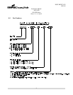
The sign is shipped set for a Ferro
-resonant Type L-828 Regulator
as illustrated in Table 1
sign power supply circuit card
jumper according to Table 2.
Return power to series circuit and verify sign illuminates through all Regulator brightness steps.
DOCUMENT 1025
REV. B
in order to isolate the transformer
from direct
The Series Isolation Transformer secondary cable should then be inserted from
inside the housing up the conduit elbow. Using the two 40762 retainers supplied with the sign
(looks
like a cupped washer with a slot), placing one below the secondary cable receptacle (L
-823 Style 8,
looks like a ball), and one above. The bottom cupped washer sits on the conduit elbow top inside the
ondary cable from dropping back down the conduit.
The top cupped washer prevents the secondary cable from being pulled out of the ground allowing the
sign power cord to disconnect if the sign is impacted and shears off at its frangible couplings. If a
nsolidating harness is used or a secondary cable extension (use electrical tape around connecti
on) is
(split clamp with screws and hex nuts) retainer supplied with the sign. Secure
823 Style 7, looks like a
straight tube) that will exit the conduit elbow. The top of the secondary receptacle should be at least
n for shipping damage upon arrival and in all cases,
Lower the sign with the legs and flanges into place. Plug the sign power cable plug into the secondary
heck the sign itself with a long carpenter’s
frangible couplings from the
sign, unscrewing the frangible couplings from the floor flanges. Install the floor flanges onto the sign
anchor bolts. Level the floor flanges for ease of installation of the sign. A long carpenter’s level can
be placed across the top of the floor flanges to be sure they are all in line and level. Do not tighten the
ntil the frangible couplings are installed back into to floor
: Some vertical adjustments can be obtained by rotating the floor flanges a turn or
pad before tightening the anchor bolts.
Shim and grout as required. Once the sign has been leveled, attach the sign tether to the closest
: Anchor hardware is not supplied with the
hardware should be corrosion resistant. The sign body must not be bent or distorted due
to an uneven installation procedure. Install a bare #14 AWG minimum copper ground wire to the
epts #4 through #14 AWG)
as illustrated in Table 1
. For other
Return power to series circuit and verify sign illuminates through all Regulator brightness steps.