


10.3
Measuring Input Curre
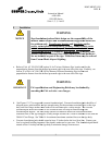
WARNING
Failure to turn off power to the sign and wait five minutes could result
in severe injury or death.
Turn off power to the sign
by turning off
(WARNING: W
ait five minutes after sign power is turned off
any residual high voltage
stored in Power Supply
multimeter set to DC Volts, verify that the Power Supply
(Positive lead) and TP3 (Negative Lead) as indicated in Figure 22. If the Power Supply Output Voltage
is greater than 30-
VDC, then you must wait until the Power Supply Output Voltage drops below 30
before yo
u proceed with the next step.
Open Power Supply cover
(See Figure
Supply Board. (Note: When removing female crimp
Disconnect female crimp recept
acle from CN18 and connect to CN17. Place current clamp around
primary power wire and connect to a true rms
measure between 2.7-
ARMS and 6.7
Upon completing the measurement of the input current, turn off power to the CCR.
clamp. Disconnect the female
crimp receptacle at CN17 and reconnect to CN18. Reconnect the female
crimp receptacle attached to wire BRPH to CN18.
10.4
Measuring Input Current (Signs
WARNING
Failure to turn off power to the sign and wait five minutes could result
in severe injury or death.
Turn off power to sign by toggling sig
to the sign. (WARNING: W
ait five minutes after sign power is turned off
will allow any residual high voltage
your multimeter set to DC Volts, verify that the Power Supply Output Voltage is less than 30
TP6 (Positive lead) and TP3 (Negative Lead) as indicated in Figure 22. If the Power Supply Output
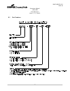
Instruction Manual
AGS-LED
858 LED Series
Sizes 1, 2, 3, 4 and 5
10
Measuring Input Curre
nt (Signs Without Optional Power Switch)
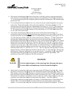
WARNING:
Failure to turn off power to the sign and wait five minutes could result
in severe injury or death.
by turning off
the corresponding
Constant Current Regulator (CC
ait five minutes after sign power is turned off
to service the sign
. This will allow
stored in Power Supply
PCB components to bleed off
. ) With your
multimeter set to DC Volts, verify that the Power Supply
Output Voltage is less than 30
(Positive lead) and TP3 (Negative Lead) as indicated in Figure 22. If the Power Supply Output Voltage
VDC, then you must wait until the Power Supply Output Voltage drops below 30
u proceed with the next step.
(See Figure
18).
Disconnect female crimp receptacle at CN17 from Power
Supply Board. (Note: When removing female crimp
receptacle, grasp by the terminal, not the wire.)
acle from CN18 and connect to CN17. Place current clamp around
primary power wire and connect to a true rms
current
meter. Turn on power to the CCR. Current should
ARMS and 6.7
-
ARMS depending on the CCR current level or current step.
Upon completing the measurement of the input current, turn off power to the CCR.
Remove the current
crimp receptacle at CN17 and reconnect to CN18. Reconnect the female
crimp receptacle attached to wire BRPH to CN18.
Close the Power Supply Box cover.
Measuring Input Current (Signs
With Optional Power Switch)
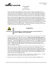
WARNING:
Failure to turn off power to the sign and wait five minutes could result
in severe injury or death.
Turn off power to sign by toggling sig
n power switch to the off position (See Figure 6)
.
ait five minutes after sign power is turned off
to service the sign
will allow any residual high voltage
stored in Power Supply PCB components to
bleed off
your multimeter set to DC Volts, verify that the Power Supply Output Voltage is less than 30
TP6 (Positive lead) and TP3 (Negative Lead) as indicated in Figure 22. If the Power Supply Output
DOCUMENT 1025
REV. B
Failure to turn off power to the sign and wait five minutes could result
Constant Current Regulator (CC
R) power.
. This will allow
. ) With your
Output Voltage is less than 30
-VDC at TP6
(Positive lead) and TP3 (Negative Lead) as indicated in Figure 22. If the Power Supply Output Voltage
VDC, then you must wait until the Power Supply Output Voltage drops below 30
-VDC
Disconnect female crimp receptacle at CN17 from Power
receptacle, grasp by the terminal, not the wire.)
acle from CN18 and connect to CN17. Place current clamp around
meter. Turn on power to the CCR. Current should
ARMS depending on the CCR current level or current step.
Remove the current
crimp receptacle at CN17 and reconnect to CN18. Reconnect the female
Failure to turn off power to the sign and wait five minutes could result
.
Turn off power
to service the sign
. This
bleed off
. ) With
your multimeter set to DC Volts, verify that the Power Supply Output Voltage is less than 30
-VDC at
TP6 (Positive lead) and TP3 (Negative Lead) as indicated in Figure 22. If the Power Supply Output