


7
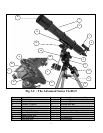
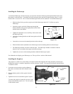
This section covers the assembly instructions for your Celestron Advanced Series Telescope (AST). Your AST
telescope should be set up indoor the first time so that it is easy to identify the various parts and familiarize yourself
with the correct assembly procedure before attempting it outdoor.
21019 / 21020
C6-R
Diameter
150mm (6.0") refractor
Focal Length
1200mm F/8
Eyepiece
20mm - 1.25" (60x)
Finderscope
9x50
Mount
CG-5 Equatorial
Tripod
2" Stainless Steel
Software
The Sky L1
Counterweight
2-11lb
S
S
e
e
t
t
t
t
i
i
n
n
g
g
u
u
p
p
t
t
h
h
e
e
T
T
r
r
i
i
p
p
o
o
d
d
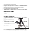
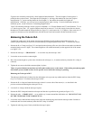
The CG-5 tripod comes with an all metal center leg brace / accessory tray to give rock solid support to the mount.
The tripod comes fully assembled with a metal plate, called the tripod head, that holds the legs together at the top.
In addition, there is a central rod that extends down from the tripod head that attaches the equatorial mount to the
tripod. To set up the tripod:
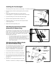
1. Stand the tripod upright and pull the tripod legs apart until each leg is fully extended. The tripod will now stand by
itself. Once the tripod is set up, you can adjust the height at
which it stands.
2. Loosen the lever on the leg clamp so that the tripod leg can be
adjusted.
3. Slide the center portion of the tripod leg away from the tripod
head until it is at the desired height.
4. Tighten the levers on each leg clamp to hold the legs in place.
A
A
t
t
t
t
a
a
c
c
h
h
i
i
n
n
g
g
t
t
h
h
e
e
E
E
q
q
u
u
a
a
t
t
o
o
r
r
i
i
a
a
l
l
M
M
o
o
u
u
n
n
t
t
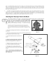
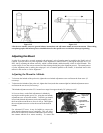
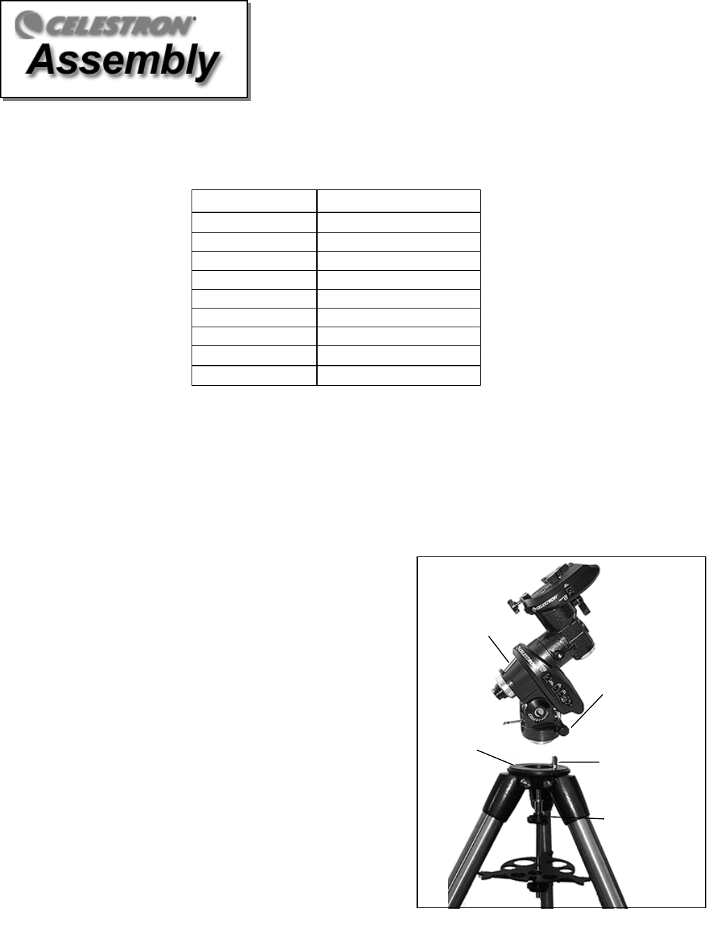
The equatorial mount allows you to tilt the telescope’s axis of
rotation so that you can track the stars as they move across the
sky. The CG-5 mount is a German equatorial mount that
attaches to the tripod head. On one side of the tripod head there
is a metal alignment peg for aligning the mount. This side of
the tripod will face north when setting up for an astronomical
observing session. To attach the equatorial head:
Equatorial
Moun
t
Tripod
Head
Alignment
Peg
Azimuth
Alignment Screws
Mounting
Knob
Figure 2-3