


13
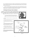
Like the R.A. balance, these are general balance instructions and will reduce undue stress on the mount. When taking
astrophotographs, this balance process should be done for the specific area at which the telescope is pointing.
A
A
d
d
j
j
u
u
s
s
t
t
i
i
n
n
g
g
t
t
h
h
e
e
M
M
o
o
u
u
n
n
t
t
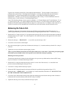
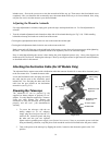
In order for a motor drive to track accurately, the telescope’s axis of rotation must be parallel to the Earth’s axis of
rotation, a process known as polar alignment. Polar alignment is achieved NOT by moving the telescope in R.A. or
DEC, but by adjusting the mount vertically, which is called altitude, and horizontally, which is called azimuth. This
section simply covers the correct movement of the telescope during the polar alignment process. The actual process
of polar alignment, that is making the telescope’s axis of rotation parallel to the Earth’s, is described later in this
manual in the section on “Polar Alignment.”
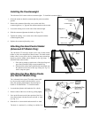
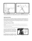
Adjusting the Mount in Altitude
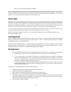
• To increase the latitude of the polar axis, tighten the rear latitude adjustment screw and loosen the front screw (if
necessary).
• To decrease the latitude of the polar axis, tighten the front (under the counterweight bar) latitude adjustment screw
and loosen the rear screw (if necessary).
The latitude adjustment on the CG-5 mount has a range from approximately 30° going up to 60°.
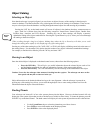
It is best to always make final adjustments in altitude by
moving the mount against gravity (i.e. using the rear latitude
adjustment screw to raise the mount). To do this you should
loosen both latitude adjustment screws and manually push
the front of the mount down as far as it will go. Then tighten
the rear adjustment screw to raise the mount to the desired
latitude.
For Advanced GT users, it may be helpful to remove the
front latitude adjustment screw completely. This will allow
the mount to reach lower latitudes without the screw coming
into contact with the R.A. motor assembly. To remove the
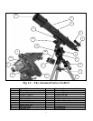
Figure 2-14
Azimuth
Adjustment
Knobs
Rear Latitude
Adjustment
Screw
Front Latitude
Adjustment Screw
Figure 2-13
Figure 2-12