


®
3
10
INSTALLING THE W-85 WALL CONTROL
1.UseonlytheCasablancaW-85wallcontrol.
2. Do not use any additional control with your Inteli-Touch
3fan(forexample,dimmer,orfanspeedcontrol).
3.Donotusemorethanonefanperwallcontrol.
4.Nootherlightxturesorelectricalappliancesmaybe
connectedonthecircuitcontrolledbytheW-85wall
control.
W-85isusedtodescribeeitherwhite(-11)oralmondnish.
IfyouhavemultipleInteli-Touch3fans,refertothesection
"ChangingFrequencySetting"onpage13.
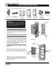
1.Removethescrewsandswitchplatefromtheexistingswitch
box.
2.Removethescrewsholdingtheswitchintheswitchbox.
3.Pulltheexistingswitchfromtheswitchboxtoexposethewire
connections.
4.Removethetwowiresfromtheswitch.
5.ConnecttheBLACKwirefromthePOWERSOURCEthatyou
justremovedfromtheswitchtotheBLACK/WHITESTRIPwire
ontheW-85wallcontrol.Securethisconnectionwithawire
nut.
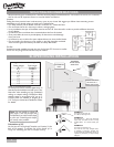
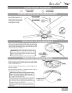
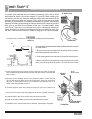
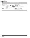
The wall control installs in the same manner as an ordinary light switch, using an existing wall box and wiring. This
controller is designed to signal the fan microcomputer as well as perform normal switching operations. For this
reasonthefollowingprecautionsmustbeobserved:
CAUTION!
EnsurepoweristurnedOFFatthebreakerorfusepanelbeforestartinginstallation.
NOTE: The REDwire is not used in this
application, DO NOT remove the crimped cap
from the wire..
BLACK AND WHITE
STRIPED WIRE
W-85
Wall Control
2 BLACK
WIRES
RED WIRE
NOT USED
(FIGURE #2)
(FIGURE #1)
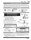
NOTE: W-85 Wall Control should only be installed on Casablanca's Inteli-Touch
®
3 fans with DOWNLIGHTS ONLY.
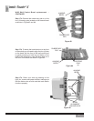
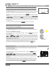
6.ConnectthesecondBLACKwirethatyoujust
removedfromtheswitchtothesecondBLACK
wireonthelocatedonthebackoftheW-85wall
control.Securethisconnectionwithawirenut.
7. Connect the green ground wire coming from the
backoftheW-85controltothegroundwireinthe
switchbox.Securethesplicewithawirenut.
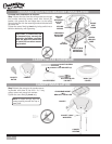
8. Check your work by using the wiring diagrams as
shown in Figures # 1 and #2.
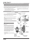
9.InstalltheW-85inthewallboxwiththetwolong
screws provided.
10.Installthewallplatewiththetwocolor-matched
screws.
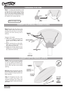
SINGLE W-85 INSTALLATION
W-85