


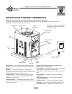
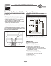
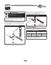
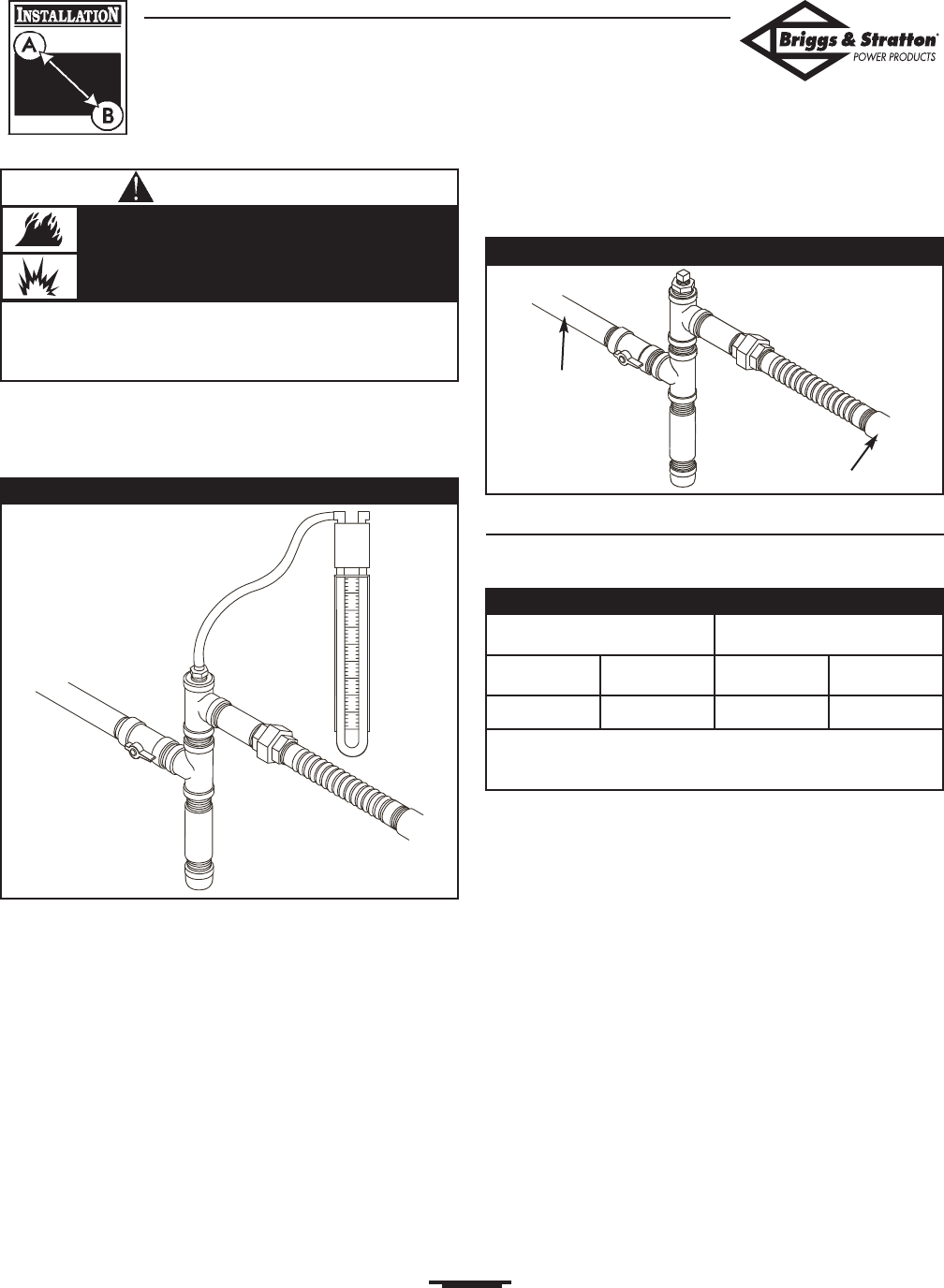
The manometer port permits temporary installation of a
manometer (Figure 5), to ensure that the engine receives
the correct fuel pressure to operate efficiently throughout
its operating range.
NOTE: A digital manometer, P/N 19495, is available at your
local Briggs and Stratton Power Products service center.
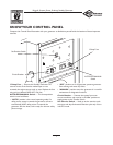
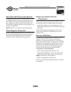
When the initial test runs are completed, the manometer is
removed and the port is plugged.A typical final fuel
connection assembly is shown in Figure 6.
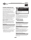
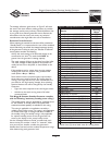
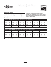
Fuel Consumption
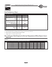
See Figure 7 for fuel supply requirements at half and full
load for both natural gas and LP vapor.
13
Briggs & Stratton Power Products Standby Generator
Installation, Start-Up and Owner’s Manual
• Before placing the Standby Generator into service, the fuel
system lines must be properly purged and leak tested.
• NO leakage is permitted.
Propane and Natural Gas are extremely
flammable and explosive.
Fire or explosion can cause severe burns or
death.
WARNING
Figure 6 — Completed Fuel Connections
From Fuel
Supply Line
To Standby
Generator
Figure 5 — Temporary Manometer Installed
Natural Gas* LP Vapor**
1/2 Load Full Load 1/2 Load Full Load
80 137 33 56
* = Natural Gas is in cubic feet per hour
** = LP Vapor is in cubic feet per hour
Figure 7 — Fuel Supply Requirements