


11
Briggs & Stratton Power Products Standby Generator
Installation, Start-Up and Owner’s Manual
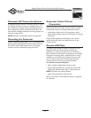
Disconnect Box Mounting Guidelines
The disconnect box is a NEMA Type 3R enclosure suitable
for outdoor use.
Guidelines for mounting the disconnect box include:
• The disconnect box must be installed with appropriate
hardware for conduit connections.
• Install the disconnect box on a firm, sturdy supporting
structure, making sure it is level and plumb.
• NEVER install the disconnect box where any corrosive
substance might drip onto the enclosure.
• Protect the disconnect box at all times against excessive
moisture, dust, dirt, lint, construction grit and corrosive
vapors.
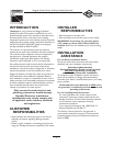
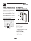
The typical installation of the disconnect box is depicted in
Figure 3. Discuss layout suggestions/changes with the owner
before beginning the installation process.
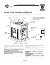
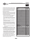
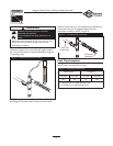
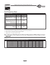
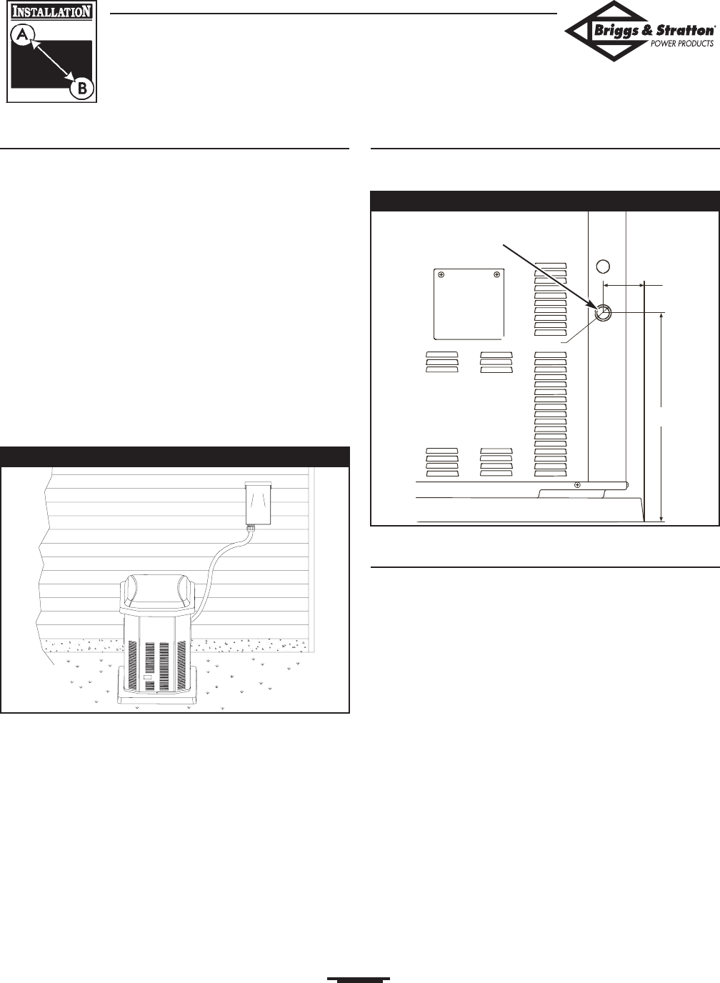
Fuel Inlet Dimensions
Figure 4, below, depicts the location of the fuel piping
connector.
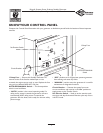
Removable Roof and Access Door
The Standby Generator is equipped with an enclosure that
has a removable roof and an access door for the control
panel.
To Remove Roof:
Remove the four screws and lift off.
To Remove Access Door:
1. Remove roof as described above.
2. Remove screw at top of access door.
3. Pull access door outward (away) from unit while
pulling door upward and out of base. Door will come
free of generator enclosure.
To Install Access Door and Roof:
1. Guide bottom of access door into base.
2. Push access door until it is flush with sides.
3. Replace door screw.
4. Replace roof and screws.
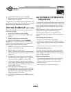
Figure 4 — Generator Fuel Attachment Location
3/4” NPT
Fuel Piping
Connector
4.5”
13.5”
Figure 3 — Typical Disconnect Box Mounting