


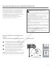
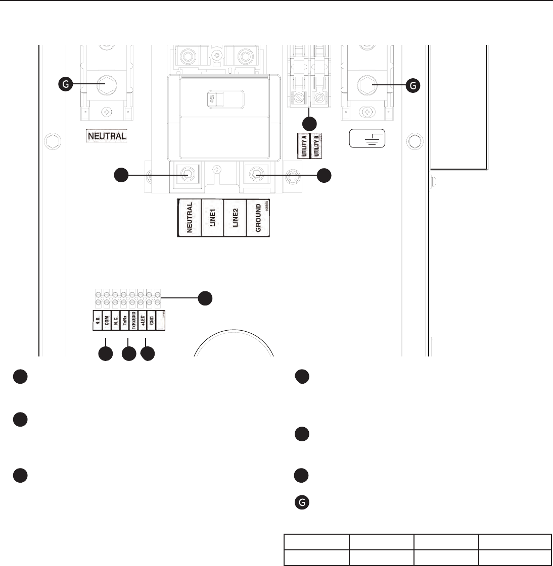
21
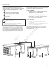
Low Voltage connections to signal fault contacts, transfer switch communication and auxiliary 12VDC power are made via a
field connection terminal block in control board area. Compare this illustration with your generator to familiarize yourself with
the location of these connections.
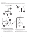
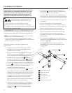
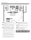
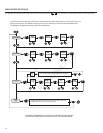
System Connectors
A ‑ Fuse Block — Used to connect utility 240 VAC from
fuse block in ATS to the control board. Connect only
one wire per terminal.
B ‑ Fault Contacts — Use NO, COM and NC to hook
up a siren, light, etc. to alert you in case of a fault.
Contacts reverse state (NO goes to NC and vice
versa) upon a fault condition.
C ‑ Transfer Switch Communication (TxRx and TxRx
GND) — Connect to transfer switch control board for
communication interface using 18AWG twisted pair
wire. (Not applicable with all transfer switches.)
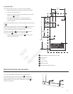
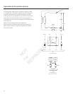
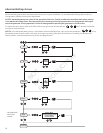
• For power output connection, use 300 volt, 167 °F-
194 °F (75 °C-90 °C) wire. See chart on right for proper
wire size.
• For Utility Circuit connection use #14 AWG minimum
300 volt, 167 °F-194 °F (75 °C-90 °C) wire.
• For transfer switch communication use #18 AWG
twisted pair conductors, no greater than 200 ft (60 m)
in length, 300 volt, 167 °F-194 °F (75 °C-90 °C) wire.
• When connecting to the ten-pin connector plug,
fasten only one wire to each connector screw.
• Torque connector plug screws to 7 in-lb (7.9 Newton meter).
GND
C
E
D
A
B
D ‑ +LED and GND Connection — Not required for
optional wireless monitor. Available for optional
hardwired remote system status panel accessory,
#6154.
E ‑ Eight Pin Terminal Block — Used to connect signal
wires to the control board. Connect only one wire per
terminal.
F ‑ Power Connection (Line 1 and Line 2) — Power
connection to transfer switch.
G ‑ Neutral and/or Ground Connection — Connect to
transfer switch neutral and ground
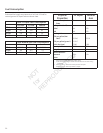
* Series Voltage Rated Amps Wire Size
Single Phase 120/240 146 2/0
*Refer to Generator Data Tag to determine series of generator.
[
[
[
F
F
A
B
C
D
E
F
NOT
for
REPRODUCTION