


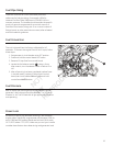
15
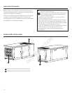
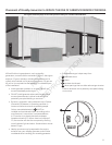
Concrete Slab
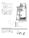
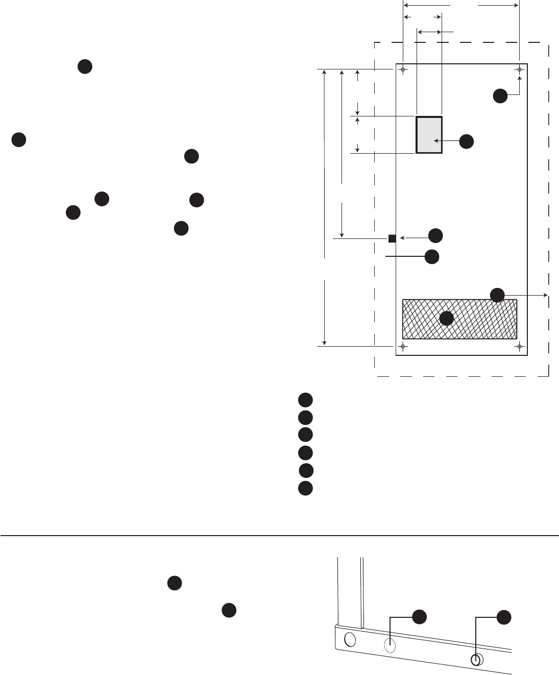
At the appropriate location, construct a concrete slab:
• 28 day compression strength of 3000 psi (200 MPa)
• Minimum 5” (13cm) thick
• Minimum 6” (15cm) wider than enclosure on all sides
(shown as D in figure)*
• Strengthen slab with No. 6 reinforcing bars (on
12” (30.5cm) centers) or 8 ga. steel wire fabric (6”
(15cm) centers).
Avoid placing reinforcement in entrance stub-up area (shown
as (B ).
Attach unit to slab at four corner locations (A) with minimum
5/16” diameter (8mm) (per local requirements) masonry
anchor bolts long enough to secure the unit.
The fuel inlet location (C) ,the concrete slab, and the
exhaust outlet (E) are shown for reference.
• The standby generator enclosure F measures 96”
(234 cm) X 37” (94 cm).
34-1/4”
87cm
14-3/4”
37.5cm
92”
233.7cm
51”
129.5cm
6”
15.2cm
5”
12.7cm
7-1/2”
19cm
C
D
A
B
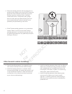
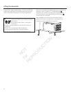
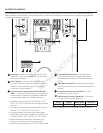
Electrical and Fuel Inlet Locations
A through-slab power cable stub-up is preferred (see
figure above). If stub-up’s are not used, (F) indicates the
recommended location for punching holes for attaching
power conduit. The 1 inch N.P.T. fuel inlet connector (C) is
shown for reference.
C
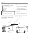
A Holes located in base to anchor to pad
B Stub up Area
C Fuel Inlet
D Concrete slab
D Exhaust Outlet
D Standby Generator Enclosure
B
C
D
A
D
D
C
B
A
F
C
F
E
E
E
F
F
F
NOT
for
REPRODUCTION