


20
Briggs & Stratton Power Products Home Standby Generator
Installation, Start-Up and Operator’s Manual
SPECIFICATIONS
Rated Maximum Power (LP*) . . . . . . . . . . . . . . . . . .7.0 kW
Rated Maximum Load Current:
at 240 Volts . . . . . . . . . . . . . . . . . . . . . . . . . . . .29.1 Amps
at 120 Volts . . . . . . . . . . . . . . . . . . . . . . . . . . . .58.2 Amps
Rated AC Voltage . . . . . . . . . . . . . . . . . . . . . . .120/240 Volts
Rated Frequency . . . . . . . . . . . . . . . . . .60 Hz at 3600 rpm
Phase . . . . . . . . . . . . . . . . . . . . . . . . . . . . . . . . .Single Phase
Power Factor . . . . . . . . . . . . . . . . . . . . . . . . . . . . . . . . . .1.0
NG Fuel Supply Pressure . . . . . . . . . . . . . . . . . .5-7 in W.C.
LP Fuel Supply Pressure . . . . . . . . . . . . . . . . .11-14 in W.C.
Normal Operating Range -20°F (-28.8°C) to 104°F (40°C)
Output Sound Level . . .81 dB(A) at 23 ft. (7 m) at full load
Shipping Weight . . . . . . . . . . . . . . . . . . . . . . . . . . . .280 lbs.
* Natural gas rating will depend on specific fuel but typical
derating of generator is between 10 to 20% off the LP gas
rating.
AUTOMATIC OPERATION
To select automatic operation, do the following:
1. Set service disconnect or main distribution panel
circuit breaker that sends utility voltage to transfer
switch to ON.
2. Set generator’s main circuit breaker to ON position.
3. Set AUTO/OFF/MANUAL switch to AUTO.
Checking Automatic Operation
To check the system for proper automatic operation,
proceed as follows:
1. Turn OFF service disconnect or main distribution
panel circuit breaker sending power to automatic
transfer switch.
The generator will crank and start once the utility voltage
drops out and the sensor has timed out. Let the system go
through its entire automatic operation sequence.
2. With generator output supplying load, turn ON
service disconnect or main distribution panel circuit
breaker that supplies utility power to automatic
transfer switch.
3. Automatic transfer switch will transfer loads back to
utility power after five minute minimum run time and
utility is restored.
4. Generator will run for approximately an additional
minute for engine cool down, then shut down.
5. Install control panel access door and roof following
instructions in “Removable Roof and Access Door” on
page 11.
NOTE: If generator does not shut down after
approximately 10 minutes, put AUTO/OFF/MANUAL
switch to OFF and contact your local service center.
This completes the test procedures for automatic
operation.The Home Standby Generator will now start
automatically when utility power is lost and will supply
power to the transfer switch.
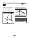
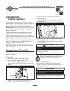
Servicing the System
To service system:
1. Remove roof by removing four screws and lifting off.
2. Remove screw at top of control panel access door.
3. Pull access door outward (away) from unit while
pulling door upward and out of base. Door will come
free of generator enclosure.
4. Set AUTO/OFF/MANUAL switch to OFF.
5. Set generator’s main circuit breaker to OFF position.
6. Pull service disconnect from disconnect box.
7. Remove 15A fuse from control panel.
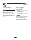
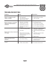
FAULT DETECTION
SYSTEM
The generator may have to run for long periods of time
with no operator present. For that reason, the system is
equipped with sensors that automatically shut down the
generator in the event of potentially damaging conditions,
such as low oil pressure, over speed, and other conditions.
A light on the remote LED plate is called the Diagnostic
LED.The LED will turn on and off in a series of blinks if
certain problems are detected in your Home Standby
Generator.The blink pattern is repeated with a brief pause