


14
Briggs & Stratton Power Products Home Standby Generator
Installation, Start-Up and Operator’s Manual
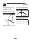
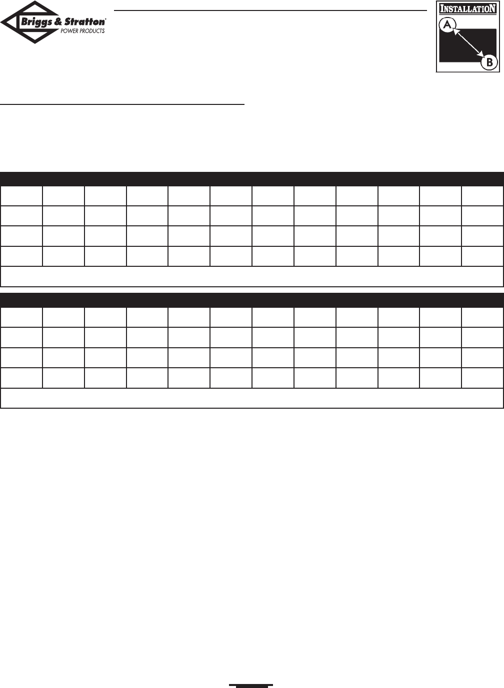
Fuel Pipe Sizing
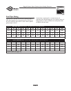
Figures 8 and 9 provide the maximum capacity of pipe in
cubic feet of gas per hour for gas pressures of 0.5 psi or
less and a pressure drop of 0.3 in. water column. Specific
gravity of gas is shown.
Listed values compensate for a nominal amount of
restriction from bends, fittings, etc. If an unusual number of
fittings, bends, or other restrictions are used, please refer
to federal and local codes.
NPT 10ft 15ft 20ft 30ft 40ft 50ft 60ft 70ft 80ft 90ft 100ft
1/2” 168 146 115 93 79 70 63 59 55 51 48
3/4” 346 293 240 192 163 145 132 120 113 106 99
1” 653 549 446 360 307 274 250 230 211 197 187
Natural Gas (sg=0.65)
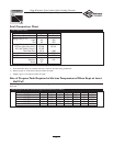
NPT 10ft 15ft 20ft 30ft 40ft 50ft 60ft 70ft 80ft 90ft 100ft
1/2” 110 96 76 61 52 46 42 38 36 33 32
3/4” 277 192 158 126 107 95 87 79 74 69 65
1” 428 360 293 236 202 180 164 151 139 129 123
Liquid Propane (LP) (sg=1.50)
Figure 8 — NATURAL GAS (NG) Pipe Size - Gas Flow Chart, in cubic feet per hour
Figure 9 — LIQUID PROPANE (LP) GAS Pipe Size - Gas Flow Chart, in cubic feet per hour