


• Where the formation of hydrates or ice is known to
occur, piping should be protected against freezing.The
termination of hard piping should include a sediment trap
where condensate is not likely to freeze.
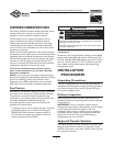
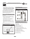
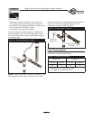
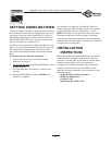
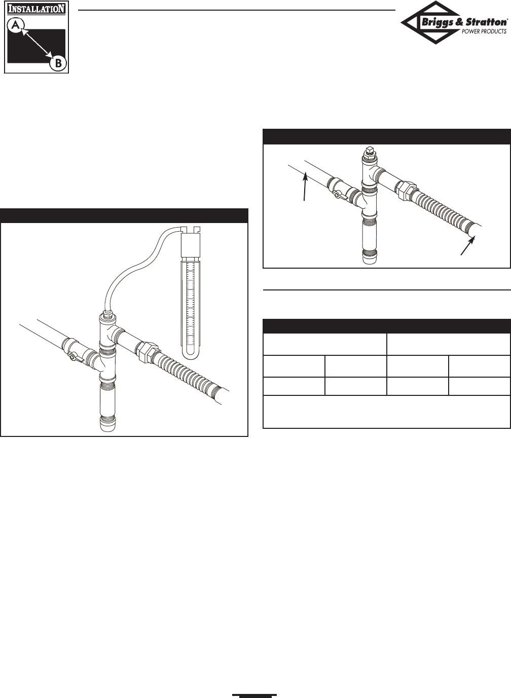
• A manometer port should be provided.
The manometer port permits temporary installation of a
manometer (Figure 5), to ensure that the engine receives
the correct fuel pressure to operate efficiently throughout
its operating range.
NOTE: A digital manometer, P/N 19495, is available at your
local Briggs and Stratton Power Products service center.
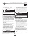
When the initial test runs are completed, the manometer is
removed and the port is plugged.A typical final fuel
connection assembly is shown in Figure 6.
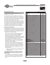
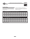
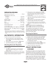
Fuel Consumption
See Figure 7 for fuel supply requirements at half and full
load for both natural gas and LP vapor.
13
Briggs & Stratton Power Products Home Standby Generator
Installation, Start-Up and Operator’s Manual
Figure 6 — Completed Fuel Connections
From Fuel
Supply Line
To Home Standby
Generator
Figure 5 — Temporary Manometer Installed
Natural Gas* LP Vapor**
1/2 Load Full Load 1/2 Load Full Load
80 137 33 56
* = Natural Gas is in cubic feet per hour
** = LP Vapor is in cubic feet per hour
Figure 7 — Fuel Supply Requirements