


12
Briggs & Stratton Power Products Home Standby Generator
Installation, Start-Up and Operator’s Manual
THE GASEOUS FUEL
SYSTEM
Consult with the Home Standby Generator owner(s) and
convey any technical considerations that might affect their
installation plans before applying these general guidelines.
The following general rules apply to gaseous fuel system
piping:
• The piping should be of a material that conforms to
federal and local codes, rigidly mounted and protected
against vibration.
• Piping should be protected from physical damage where
it passes through flower beds, shrub beds, and other
cultivated areas where damage could occur.
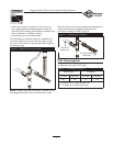
• Install the flexible, gaseous hose (supplied) between the
Home Standby Generator Fuel Inlet port and rigid piping
to prevent thermal expansion or contraction from
causing excessive stress on the piping material.
NOTE:Where local conditions include earthquake,
tornado, unstable ground, or flood hazards, special
consideration shall be given to increase strength and
flexibility of piping supports and connections.
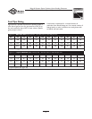
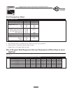
• Piping must be of the correct size to maintain the
required supply pressures and volume flow under varying
generator load conditions with all gas appliances
connected to the fuel system turned on and operating.
• Use an approved pipe sealant or joint compound on all
threaded fittings to reduce the possibility of leakage.
• Installed piping must be properly purged and leak tested,
in accordance with applicable codes and standards.
Consider the following factors when planning to
install the fuel supply system:
The Home Standby Generator engine is fitted with a fuel
mixer system that meets the specifications of the California
Air Resources Board for “tamper-proof” dual fuel systems.
The unit will run on natural gas or liquefied propane.
• A minimum of one accessible, approved manual shutoff
valve shall be installed in the fuel supply line within 6 ft
(1.8 m) of the Home Standby Generator.A union or
flanged connection shall be provided downstream from
this valve to permit removal of controls.
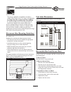
• Natural gas fuel supply pressure at the generator's fuel
inlet port should be between 5 to 7 inches of water (in.
W.C.) at full load. LP fuel supply pressure should be 11 to
14 inches of water (in.W.C.) at full load.
The Home Standby Generator unit has been
factory set to run on natural gas. If you need to
change from natural gas to LP gas, the unit will need to be
reconfigured, as described on page 18.
It is recommended that the fuel connection incorporate
the following components:
• A manual fuel shut-off valve located in the interior of the
building.
• A manual fuel shut-off valve located outside the building,
just before the generator unit.
• The entire flexible gaseous pipe must be visible for periodic
inspection and must not be concealed within, contact,or run
through any wall, floor, or partition.
The supplied flexible gaseous pipe is not to be installed
underground or in contact with the ground.
CAUTION
• Before placing the Home Standby Generator into service, the
fuel system lines must be properly purged and leak tested.
• NO leakage is permitted.
Propane and Natural Gas are extremely
flammable and explosive.
Fire or explosion can cause severe burns or
death.
WARNING
The information provided below is to assist
gaseous fuel system technicians in planning
installations. In no way should this information
be interpreted to conflict with applicable fuel gas
codes. Consult with your local fuel supplier or
Fire Marshall if questions or problems arise.
• LP gas is heavier than air and will settle in low areas.
• Natural gas is lighter than air and will collect in high areas.
• The slightest spark can ignite these fuels and cause an explosion.
Propane and Natural Gas are extremely
flammable and explosive.
Fire or explosion can cause severe burns or
death.
WARNING