


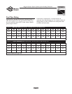


18
Briggs & Stratton Power Products Home Standby Generator
Installation, Start-Up and Operator’s Manual
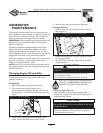
FUEL SYSTEM SELECTION
The engine of your Home Standby Generator is factory
calibrated to run on natural gas (NG). It may also be
operated on liquid propane (LP).
To configure the fuel system for LP use:
1. LP fuel inlet pressure must be between 11 and
14 inches water column.
2. Set AUTO/OFF/MANUAL switch to OFF.
3. Pull service disconnect from disconnect box.
4. Remove 15 Amp fuse.
5. Change main jet in fuel mixer following instruction
sheet provided in LP conversion kit.
6. Reinstall 15 Amp fuse.
7. Reinstall service disconnect in disconnect box.
8. Set AUTO/OFF/MANUAL switch to AUTO.
9. Reset exercise timer following instructions “Setting
Exercise Timer” on page 19.
The generator is now ready to operate automatically using
LP fuel.With a fixed main jet for LP gas, there is no need to
perform any engine adjustments for LP operation.
INITIAL START-UP (NO LOAD)
Begin testing the generator without any electrical loads
connected, as follows:
1. Set AUTO/OFF/MANUAL switch to OFF.
2. Set generator’s main circuit breaker to OFF (open)
position.
3. Install 15 Amp fuse in control panel.
4. Set AUTO/OFF/MANUAL switch to MANUAL.
NOTE:When the Home Standby Generator is started for
the very first time, it will require that air in the gaseous fuel
lines be purged.This may take a few minutes.
5. DO NOT crank engine for more than 15 seconds, then
pause for 15 seconds to reduce heat in starter.
6. Repeat process until engine starts.
7. Listen for unusual noises, vibration or other indications
of abnormal operation. Check for oil leaks while the
engine runs.
8. Let engine warm up for about five minutes to allow
internal temperatures to stabilize.Then, set generators
main circuit breaker to ON (or closed) position.
9. Connect an RMS AC voltmeter and a frequency meter
to check generator output at load side of circuit
breaker.Voltage should be 230-240 Volts, frequency
should be 62.0 - 62.5 Hz.
10. Check generator output between one generator
connection lug and neutral lug, then between other
generator connection lug and neutral lug. In both cases,
voltage reading should be between 115-120Volts.
11. Set AUTO/OFF/MANUAL switch to OFF. Engine will
shut down.
AUTOMATIC OPERATION
SEQUENCE
The generator’s control panel houses a logic control circuit
board.This control board constantly monitors utility power
source voltage. Should that voltage drop below a preset
level, control board action will signal the engine to crank
and start.
When utility source voltage is restored above a preset
voltage level, the engine is signaled to shut down.
The actual system operation is not adjustable and is
sequenced by sensors and timers on the control board, as
follows:
Utility Voltage Dropout Sensor
• This sensor monitors utility source voltage.
• If utility source voltage drops below 70 percent of the
nominal supply voltage, the sensor energizes a six second
timer.
• Once the timer has expired, the generator will start.
Utility Voltage Pickup Sensor
This sensor monitors utility power supply voltage.When
that voltage is restored above 70 percent of the nominal
source voltage, a time delay starts timing and the generator
will go to engine cool-down.
Engine Cool-down Timer
• When the load is transferred back to the utility power
source, the engine cool-down timer starts timing.
• The timer will run for about one minute, then the
generator will stop.
• Minimum generator run time is five minutes.