


16
Briggs & Stratton Power Products Home Standby Generator
Installation, Start-Up and Operator’s Manual
WIRE CONNECTIONS
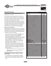
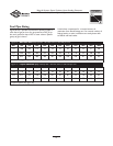
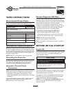
Recommended Torque Values
Torque all wire connections/fasteners to values recommended
in Figure 10. Suitable for copper wire of 60°/75°C rating.
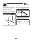
Generator AC Connection System
A single-phase, three-wire AC connection system is used in
the Home Standby Generator.The stator assembly consists
of a pair of stationary windings with two leads brought out
of each winding.The junction of leads 22 and 33 forms the
neutral lead.A complete schematic and wiring diagram can
be found on pages 26-27.
NOTE: Neutral is not bonded to ground at generator.
Grounding the Generator
Installer-supplied stranded copper wire is connected to the
disconnect box GND lug and routed through conduit to
the Transfer Switch GND. Continue the wire through
conduit to the main distribution panel ground bus.
Generator Control Circuit
Connection
Control circuit interconnections consist of "240V AC
Utility" leads.These two leads must be routed in conduit.
Control lead functions are briefly described as follows:
• Leads deliver utility power to the generator’s circuit
board, optional battery warmer and oil heater and charge
the battery.
Using installer-supplied minimum 300V, 16 AWG stranded
copper wire, connect control circuit terminals in the
disconnect box to the Transfer Switch.
Remote Diagnostic LED Plate
The light on the remote LED plate is referred to as the
Diagnostic LED.The LED will stay lit indicating the generator
is in ready mode and will turn on and off in a series of blinks
if certain faults are detected in the Home Standby
Generator.A mounting plate is supplied so that it can be
installed at a convenient indoor location.The owner will use
it to observe the status of the Home Standby Generator.
Consult with the owner for a convenient location.
To install the remote diagnostic LED plate:
• Mount installer-supplied electrical box to wall.
• Using installer-supplied wire, connect the remote LED
leads to the “Remote Status Light” in disconnect box.
NOTE: LED leads are polarity sensitive.
• Attach mounting plate to electrical box.
Refer to the section “Fault Detection System” on page 20
for operation.
BEFORE INITIAL START-UP
Engine Oil
This engine is shipped from the factory filled with the
recommended oil. Before starting the engine, check oil level
and ensure that engine is serviced as described in the
engine operator’s manual.
Oil Considerations
Your Home Standby Generator is equipped with an engine
that has been pre-run at the factory and does not require
the traditional “break-in” procedure.
The generator is filled with synthetic oil (API SJ/CF 5W-
30W).This allows for generator operation in the widest
range of temperature and climate conditions.
NOTE:The use of synthetic oil DOES NOT alter the
required oil change intervals described in the engine
operator’s manual.
CAUTION
• Refer to engine manual for oil fill information.
• Damage to equipment resulting from failure to follow this
instruction will void warranty.
Any attempt to crank or start the engine before it has
been properly serviced with the recommended oil will
result in equipment failure.
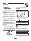
CONNECTIONS: Torque Value
In Main Distribution Panel:
Refer to panel manufacturer specs
In Disconnect Box:
240V AC Utility 5 in-lb
Engine Start 5 in-lb
Remote Status 5 in-lb
Generator 17 in-lb
Ground 40 in-lb
Circuit Breakers:
Refer to circuit breaker manufacturer specs
Figure 10 — Recommended Torque Values