


Steeri
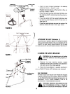
~ ~~HeX Lock Wheel ,~ Nut
,
..,r"
:--- Cupped
Washer
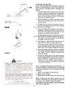
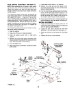
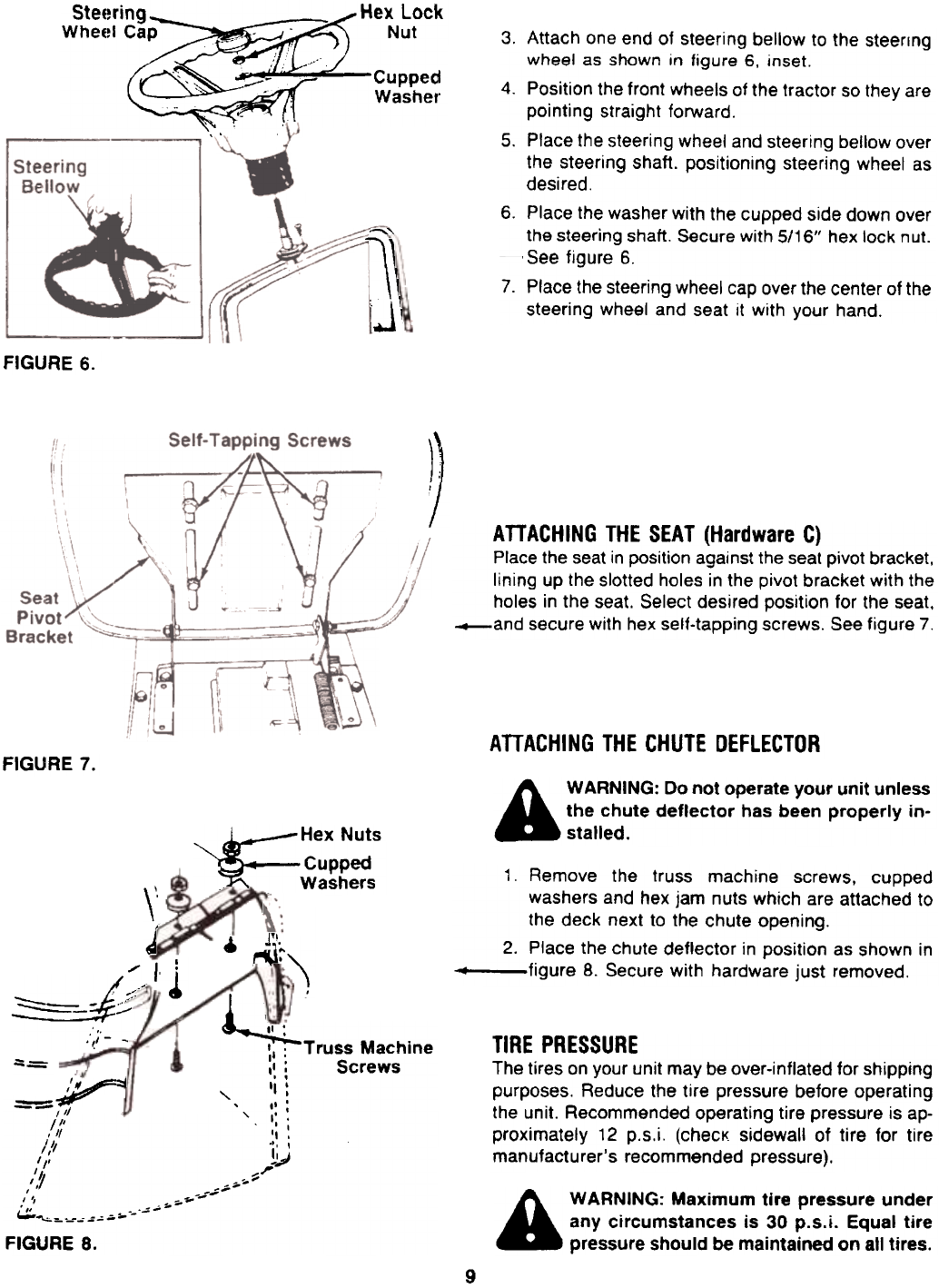
3. Attach one end of steering bellow to the steering
wheel as shown in figure 6, inset.
4. Position the front wheels of the tractor so they are
pointing straight forward.
5. Place the steering wheel and steering bellow over
the steering shaft. positioning steering wheel as
desired.
6. Place the washer with the cupped side down over
the steering shaft. Secure with 5/16" hex lock nut.
~ See figure 6.
7. Place the steering wheel cap over the center of the
steering wheel and seat it with your hand.
-"'l\
.J\
FIGURE 6.
~
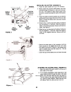
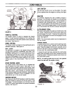
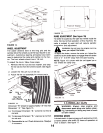
ATTACHING THE SEAT (Hardware C)
Place the seat in position against the seat pivot bracket,
lining up the slotted holes in the pivot bracket with the
holes in the seat. Select desired position for the seat,
_and secure with hex self-tapping screws. See figure 7.
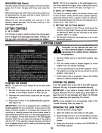
AnACHING THE CHUTE DEFLECTOR
FIGURE 7.
A WARNING: Do not operate your unit unless
the chute deflector has been properly in-
stalled.
~
Hex Nuts
Cupped
.Washers
r\l~)
\"
J
.
1. Remove the truss machine screws. cupped
washers and hex jam nuts which are attached to
the deck next to the chute opening.
2. Place the chute deflector in position as shown in
~ figure 8. Secure with hardware just removed.
/, i
/- .:.-
~~
:~I .:-~
k .. II '
:1; Truss Machine
,I : Screws
~,=.. ~ I
I':
, "I
--= ' ,.'
-III " ,':
1/1 I ,
, /1 'I ,
1/1 do ,
/, II -1
/" ,..,
/. ~ '
7 -,,--
, --
, --
-..;--
, " -..~
c:.::.~:,,-," =-, ;';"
FIGURE 8.
----
TIRE PRESSURE
The tires on your unit may be over-inflated for shipping
purposes. Reduce the tire pressure before operating
the unit. Recommended operating tire pressure is ap-
proximately 12 p.s.i. (checK sidewall of tire for tire
manufacturer's recommended pressure).
A WARNING: Maximum tire pressure under
any circumstances is 30 p.s.i. Equal tire
pressure should be maintained on all tires.
9