


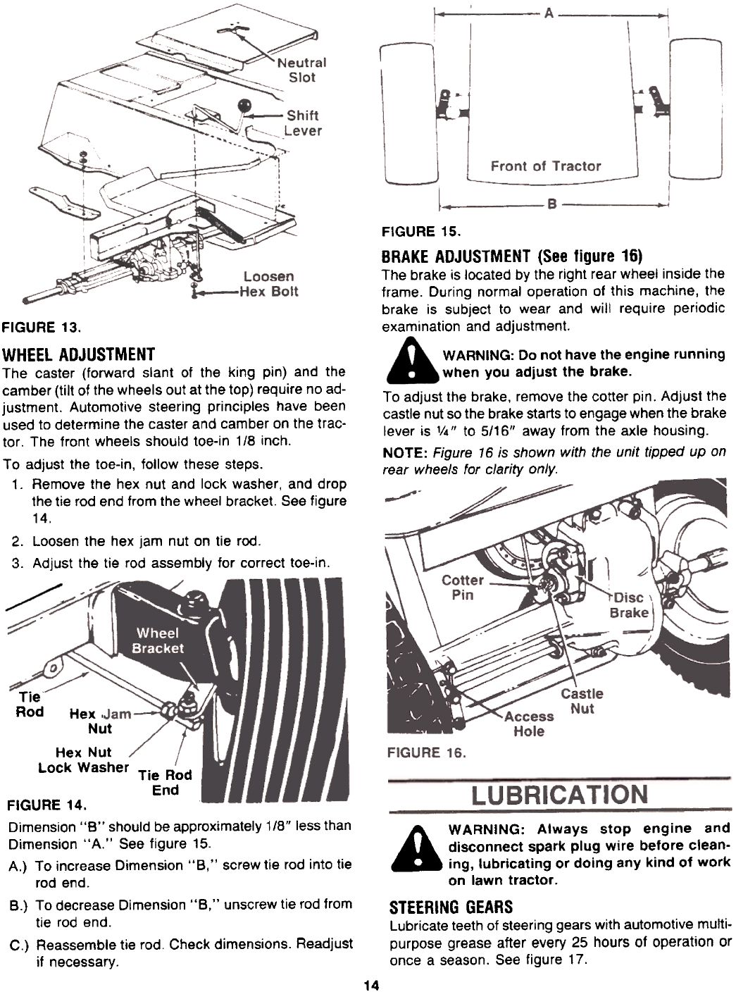
FIGURE 15.
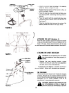
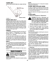
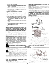
BRAKE ADJUSTMENT (See figure 16)
The brake is located by the right rear whee! inside the
frame. During normal operation of this machine, the
brake is subject to wear and will require periodic
examination and adjustment.
WARNING: Do not have the engine running
when you adjust the brake.To
adjust the brake, remove the cotter pin. Adjust the
castle nut so the brake starts to engage when the brake
lever is V4 II to 5/16" away from the axle housing.
NOTE: Figure 16 is shown with the unit tipped up onrear
wheels for clarity only.
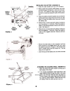
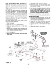
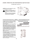
FIGURE 13.
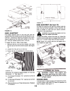
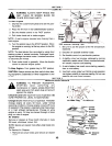
WHEEL ADJUSTMENT
The caster (forward slant of the king pin) and the
camber (tilt of the wheels out at the top) require no ad-
justment. Automotive steering principles have been
used to determine the caster and camber on the trac-
tor. The front wheels should toe-in 1/8 inch.
To adjust the toe-in, follow these steps.
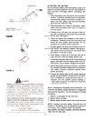
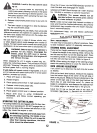
1. Remove the hex nut and lock washer, and drop
the tie rod end from the wheel bracket. See figure
14.
2. Loosen the hex jam nut on tie rod.
3. Adjust the tie rod assembly for correct toe-in.
Tie"
Rod
Hex,
Nut
Hex Nut
Lock Washer Tie Rod
End
A WARNING: Always stop engine and
disconnect spark plug wire before clean-
ing, lubricating or doing any kind of work
on lawn tractor.
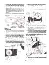
STEERING GEARS
Lubricate teeth of steering gears with automotive multi-
purpose grease after every 25 hours of operation or
once a season. See figure 17.
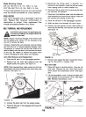
FIGURE 14.
Dimension "B" should be approximately 1/8" less than
Dimension "A." See figure 15.
A.) To increase Dimension "B," screw tie rod into tie
rod end.
B.) To decrease Dimension "B," unscrew tie rod from
tie rod end.
C.) Reassemble tie rod. Check dimensions. Readjust
if necessary.
14