


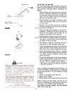
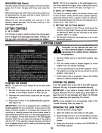
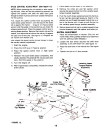
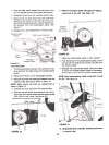
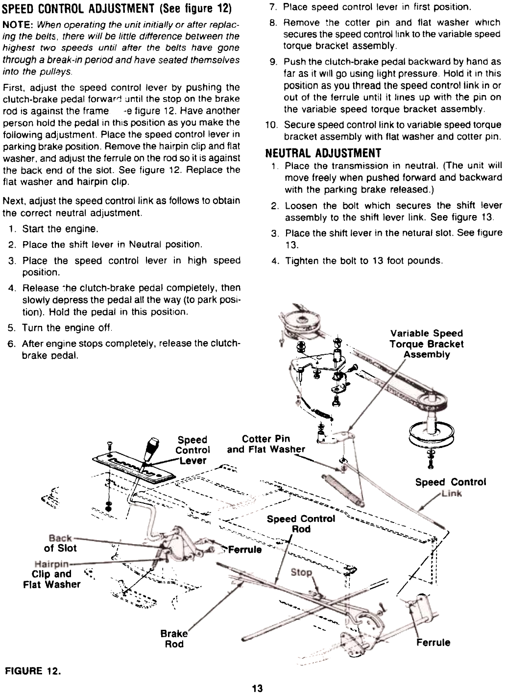
SPEED CONTROL ADJUSTMENT (See figure 12)
NOTE: When operating the unit initially or after replac-
ing the belt5. there will be little difference between the
highest two speeds until after the belts have gone
through a break-in period and have seated themselves
into the pull~ys.
First. adjust the speed control lever by pushing the
clutch-brake pedal forwaroj until the stop on the brake
rod is against the frame ..e figure 12. Have another
person hold the pedal in this position as you make the
following adjustment. Place the speed control lever in
parking brake position. Remove the hairpin clip and flat
washer. and adjust the ferrule on the rod so it is against
the back end of the slot. See figure 12. Replace the
flat washer and hairpin clip.
7. Place speed control lever in first position.
8. Remove the cotter pin and flat washer which
secures the speed control link to the variable speed
torque bracket assembly.
9. Push the clutch-brake pedal backward by hand as
far as it will go using light pressure. Hold it in this
position as you thread the speed control link in or
out of the ferrule until it lines up with the pin on
the variable speed torque bracket assembly.
10. Secure speed control link to variable speed torque
bracket assembly with flat washer and cotter pin.
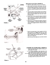
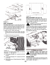
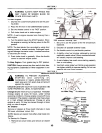
NEUTRAL ADJUSTMENT
1 Place the transmission in neutral. (The unit will
move freely when pushed forward and backward
with the parking brake released.)
2. Loosen the bolt which secures the shift lever
assembly to the shift lever link. See figure 13.
3. Place the shift lever in the netural slot. See figure
13.
4. Tighten the bolt to 13 foot pounds.
Variable Speed
Torque Bracket
Assembly
Next. adjust the speed control link as follows to obtain
the correct neutral adjustment.
1. Start the engine.
2. Place the shift lever in Neutral position.
3. Place the speed control lever in high speed
position.
4. Release ~h~ clutch-brake pedal completely, then
slowly depress the pedal all the way (to park posi-
tion). Hold the pedal in this position.
5. Turn the engine off.
6. After engine stops completely, release the clutch-
brake pedal.
~
,\
'~
~ :':"
~
Cotter Pin
and Flat Washer
Speed
Control
Lever
.'.':-. -
i~~- ~.. :;:-
.:r~",- ~ -o i:.:--:-- ~~~"
1 "(~---'- ~~:'-.! ,/ -'~': ,,' ':.;::.. --:-::'. '
~
,
~-~
Speed Contro!
~ ,,-",,-~ -'~-::.;:-~~
~- -~+... -
~",,- ,~- 'F".",--
J ~
-~
Q~ -~
"", --
" -
-~:- Speed Control "~"'" "--~_::~ -.~ ~ Rod ""O."--:;""'"' :---~ "-
-'., ~-~ --'~ -.,)
~Ferrul;"~.~. .-' --,.~(
~ --.f;
",'
.,.,~ -
~
.."""
,~
...'-~~~
of Slot
,. ,-
/;
"""
~ '~'~ --I '.
-'-- '... -
.,., -..~ ;~..
..'.. -
,.' .
~ --.+- ,
"" .~.;.::~ ';,\
~~
,- -
---
--'-.
-"""""""~
" r
,; !
/::
)l': ,I "
-::
'
Clip and
Flat Washer
.-.,-
",
::;;::::--
/
,
.~~_.~
'"'-
'+..~
--
",
...\
Brake
Rod
Ferrule
' ""
FIGURE 12.
13