


Blade Mounting Torque
3/8" Dia. Bolt 375 in. Ib, min.. 450 in. Ib, max.
5/16" Dia. Bolt 150 in. Ib, min., 250 in, Ib, max,
To insure safe operation of your unit, ALL nuts and bolts
must be checked periodically for correct tightness.
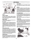
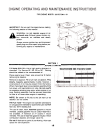
FUEL FILTER
Your unit is equipped with a replaceable in-line fuel
filter. Replace filter whenever contamination or
discoloration is noticed. Order replacement- filter
through participating Western Auto Stores.
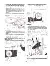
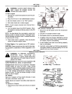
5. Disconnect the spring which is attached to a
bracket on the transaxle. inside the left rear wheel.
Use a spring puller or other suitable tool.
6. Disconnect the six deck links by removing the hair-
pin clips and flat washers.
7. Disconnect the stabilizer plate from the stabilizer
shaft assembly by removing the hairpin clips and
flat washers and sliding out the rod.
8. Place the lift lever in the disengaged position.
9. Slide the deck from beneath the lawn tractor.
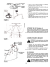
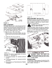
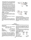
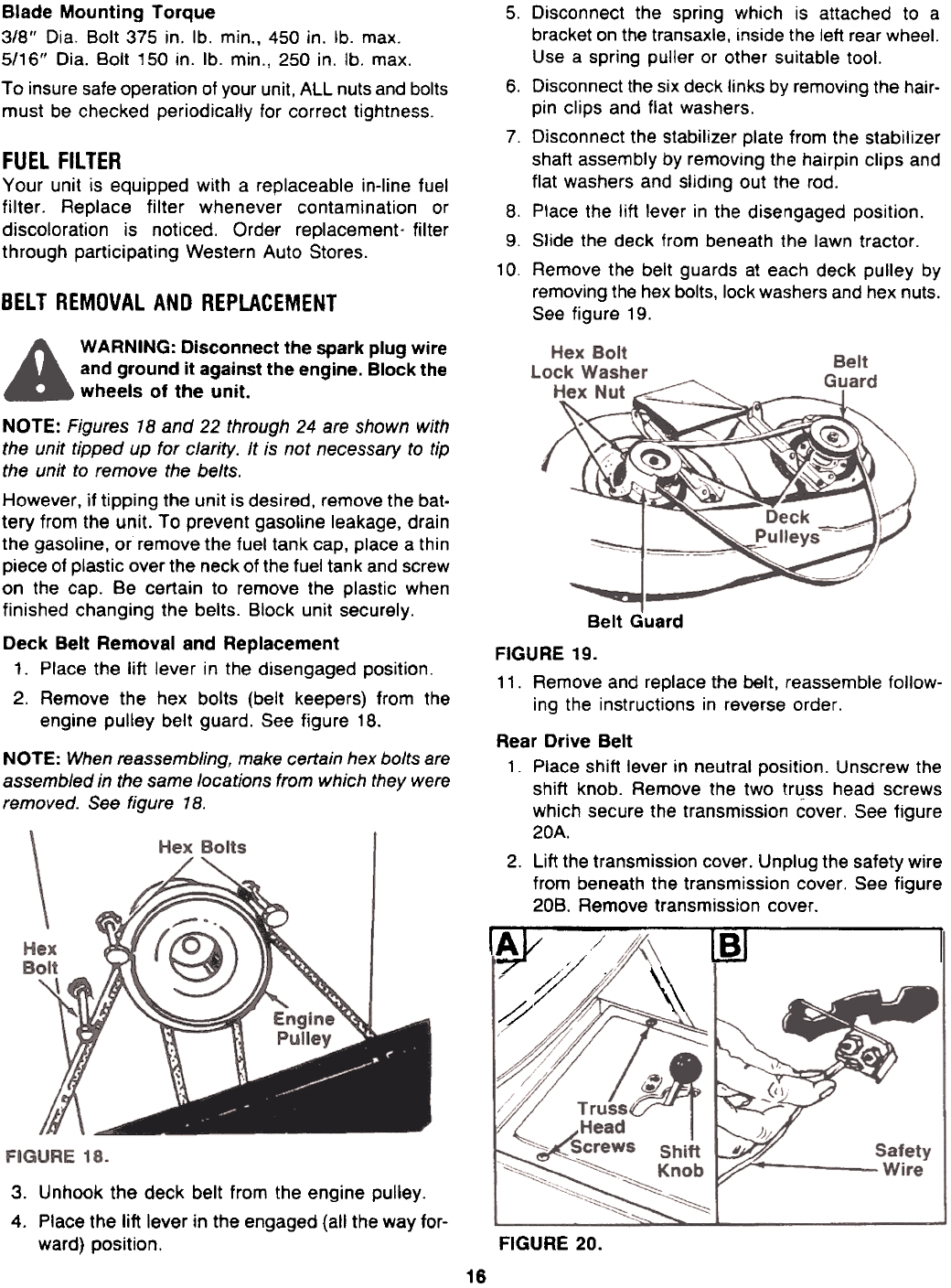
10. Remove the belt guards at each deck pulley by
removing the hex bolts, lock washers and hex nuts.
See figure 19.
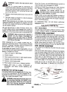
BELT REMOVAL AND REPLACEMENT
WARNING: Disconnect the spark plug wire
and ground it against the engine. Block the
wheels of the unit.
NOTE: Figures 18 and 22 through 24 are shown with
the unit tipped up for clarity. It is not necessary to tip
the unit to remove the belts.
However, if tipping the unit is desired, remove the bat.
tery from the unit. To prevent gasoline leakage, drain
the gasoline, or remove the fuel tank cap, place a thin
piece of plastic over the neck of the fuel tank and screw
on the cap. Be certain to remove the plastic when
finished changing the belts. Block unit securely.
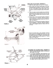
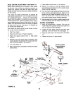
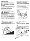
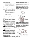
Deck Belt Removal and Replacement
1. Place the lift lever in the disengaged position.
2. Remove the hex bolts (belt keepers) from the
engine pulley belt guard. See figure 18.
NOTE: When reassembling, make certain hex bolts are
assembled in the same locations from which they were
removed. See figure 1 B.
Belt Guard
FIGURE 19.
11. Remove and replace the belt, reassemble follow-
ing the instructions in reverse order.
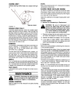
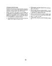
Rear Drive Belt
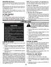
1. Place shift lever in neutral position. Unscrew the
shift knob. Remove the two truss head screws
which secure the transmission cover. See figure
20A.
2. Lift the transmission cover. Unplug the safety wire
from beneath the transmission cover. See figure
208. Remove transmission cover.
rAI/ ,-j IBI [
'7 /;/ .~ I
\\
{/~
\\
3.
Unhook the deck belt from the engine pulley.4.
Place the lift lever in the engaged (all the way for-
ward) position.
FIGURE 20.
16