


MAINTENANCE AND REPAIR INSTRUCTIONS
Go To Step 8 for SplitLine™ Installation
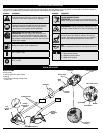
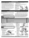
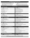
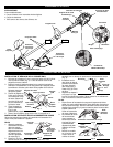
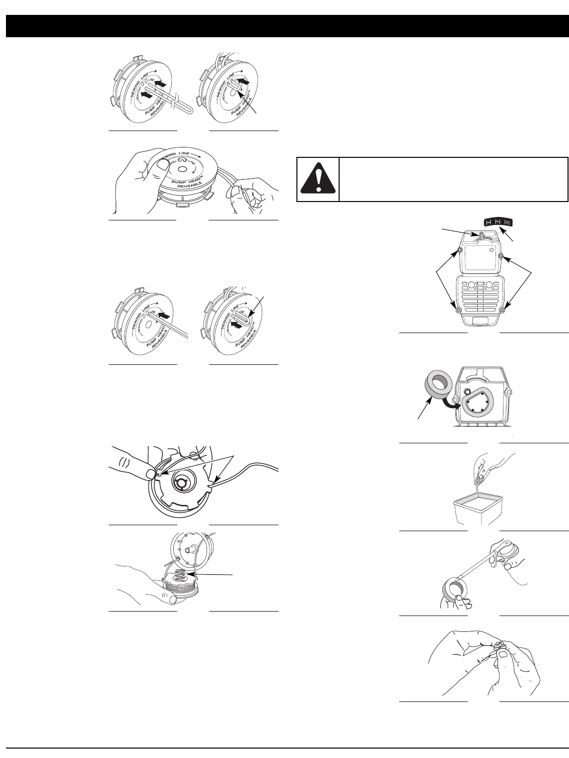
6. Take approximately
20 feet (6 m) of new
trimming line, loop it
into two equal
lengths. Insert each
end of the line
through one of the
two holes in the
inner reel (Fig. 16).
Pull the line through
the inner reel so that
the loop is as small
as possible.
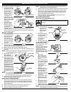
7. Wind the lines in
tight even layers,
onto the reel (Fig.
17). Wind the line in
the direction
indicated on the
inner reel. Place your index finger between the two lines to
stop the lines from overlapping. Do not overlap the ends of the
line. Proceed to step 11.
SplitLine™ Installation
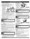
8. Take approximately 10 feet (3 m) of new trimming line. Insert
one end of the line
through one of the
two holes in the
inner reel (Fig. 18).
Pull the line through
the inner reel until
only about 4 inches
is left out.
9. Insert the end of the
line into the open hole in the inner reel and pull the line tight to
make the loop as small as possible (Fig. 18).
10. Before winding, split the line back about 6 inches.
11. Wind the line in tight even layers in the direction indicated on the
inner reel.
NOTE: Failure to wind the line in the direction indicated will cause
the cutting attachment to operate incorrectly.
12.
Insert the ends of the
line into the two
holding slots (Fig. 19).
13.
Insert the ends of the
line through the eyelets
in the outer spool and
place inner reel with
spring inside the outer
spool (Fig. 20). Push
the inner reel and outer
spool together. While
holding the inner reel
and outer spool, grasp
the ends and pull firmly
to release the line from
the holding slots in the
reel.
NOTE: The spring must
be assembled on
the inner reel before reassembling the cutting attachment.
14. Hold the inner reel in place and install the bump knob by
turning clockwise. Tighten securely.
INSTALLING A PREWOUND REEL
1. Hold the outer spool with one hand and unscrew the bump
knob counterclockwise (Fig. 12). Inspect the bolt inside the
bump knob to make sure it moves freely. Replace the bump
knob if damaged.
2. Remove the old inner reel from the outer spool (Fig. 13).
3. Remove the spring from the old inner reel (Fig. 13).
4. Place the spring in the new inner reel.
Fig. 16
Loop
NOTE: The spring must be assembled on the inner reel before
reassembling the cutting attachment.
5.
Insert the ends of the line through the eyelets in the outer spool (Fig. 20).
6. Place the new inner reel inside the outer spool. Push the inner
reel and outer spool together. While holding the inner reel and
outer spool, grasp the ends and pull firmly to release the line
from the holding slots in the spool.
7. Hold the inner reel in place and install the bump knob by
turning clockwise. Tighten securely.
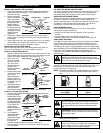
AIR FILTER MAINTENANCE
Removing the Air Filter/Muffler Cover
1. Place the blue choke lever in Position 2 (Fig. 21).
NOTE: The blue choke
lever must be in
Position 2 to
remove the air
filter/ muffler
cover.
2. Remove the four (4)
screws securing the
air filter/muffler
cover (Fig. 21). Use
a T-20 Torx bit
screwdriver.
3. Pull the cover from
the engine. Do not force.
Cleaning the Air Filter
Clean and re-oil the air filter
every 10 hours of
operation. It is an important
item to maintain. Failure to
maintain your air filter
properly can result in poor
performance or can cause
permanent damage to your
engine.
1. Remove air
filter/muffler cover.
Refer to Removing
the Air Filter/Muffler
Cover.
2. Turn cover over and
look inside to locate
the air filter. Remove
the air filter from
inside the air
filter/muffler cover
(Fig. 22).
3. Wash the filter in
detergent and water
(Fig. 23). Rinse the
filter thoroughly.
Squeeze out excess
water. Allow it to dry
completely.
4. Apply enough clean
SAE 30 oil to lightly
coat the filter (Fig.
24).
5. Squeeze the filter to
spread and remove
excess oil (Fig. 25).
6. Replace the air filter
inside the air filter/muffler cover (Fig. 22).
NOTE: Operating the unit without the air filter and air filter/muffler
cover assembly will VOID the warranty.
Fig. 17
Fig. 18
Loop
Fig. 19
Primer Bulb
Fig. 20
Spring
WARNING:
To avoid serious personal injury, always
turn your unit off and allow it to cool before you clean or
service it.
Fig. 21
Screws
Blue Choke
Lever
Screws
Position 2
Fig. 22
Inside Muffler Cover
Air Filter
Fig. 23
Fig. 24
Fig. 25
7