


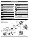
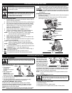
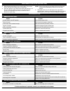
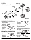
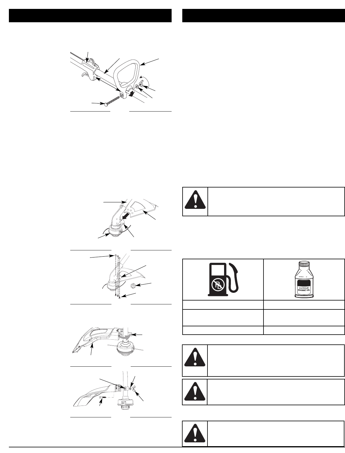
INSTALL AND ADJUST THE D-HANDLE
1. P
ush the D-handle down onto the shaft housing so that the handle
slants towards the shaft grip (Fig. 1). The squared bolt hole in the
handle is to the right.
2. Insert the shoulder
bolt into the squared
hole in the handle
and push through. On
the left side of the
handle, place the
washer on the bolt,
then screw the wing
nut onto the bolt. Do
not tighten until you
make the handle
adjustment.
3. R
otate the D-handle to place the grip above the top of the shaft
housing. Place it a minimum of 6 inches (15.24 cm) from the end of
the shaft grip.
4. While holding the unit in the operating position (Fig. 9), position
the D-handle to the location that provides you the best grip.
5. Tighten the wing nut until the D-handle is secure.
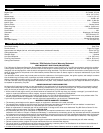
INSTALLING THE CUTTING SHIELD
Use the following instructions if the cutting attachment shield on
your unit is not installed or if you ever need to re-install it.
Install on a Straight Shaft (BL150)
1. Slide the cutting attachment shield into the shield mount on the
cutting attachment. Align the screw holes in the shield with the
holes in the cutting attachment shield mount (Fig. 2).
2. Place one of the
three (3) supplied
hex lock nuts into
one of the three
recessed holes on
the top of the
cutting attachment
shield (Fig 3).
3. I
nstall a screw into the
hole from the bottom
of the cutting
attachment shield.
Screw it into the nut
installed in step 2 until
it is started (Fig 3). Do
not tighten.
4. R
epeat steps 2 and 3
until all three screws
have been started.
Then tighten all screws securely with a Phillips head screwdriver.
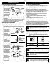
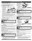
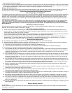
Install on a Curved Shaft (BL100)
1.
Place the cutting attachment shield onto the shaft housing. Be sure
the guard mounting
bracket slides into the
slot on the edge of the
cutting shield. Rotate
the shield into place,
counterclockwise (Fig.
4). The holes in the
guard mounting
bracket and cutting
attachment shield will
line up.
2. From inside the
cutting attachment
shield, push the
square bolt through
the hole until the
threaded end
protrudes through the guard mounting bracket (Fig. 5).
3. Put the washer on the bolt, then screw the wing nut onto the
bolt and tighten.
ASSEMBLY INSTRUCTIONS
Shaft Housing
Shield
Mount
Cutting
Attachment
Shield
Cutting
Attachment
Fig. 2
Recessed
Holes
Hex Lock
Nut
Screws (3)
Fig. 3
Nuts (3)
Guard
Mounting
Bracket
Cutting Attachment Shield
Fig. 4
Fig. 5
Square Bolt
Guard
Mounting
Bracket
Wing Nut
Washer
OIL AND FUEL INFORMATION
OIL AND FUEL MIXING INSTRUCTIONS
Old and/or improperly mixed fuel are the main reasons for the unit
not running properly. Be sure to use fresh, clean unleaded fuel.
Follow the instructions carefully for the proper fuel/oil mixture.
DEFINITION OF BLENDED FUELS
Today's fuels are often a blend of gasoline and oxygenates such
as ethanol, methanol, or MTBE (ether). Alcohol-blended fuel
absorbs water. As little as 1% water in the fuel can make fuel and
oil separate. It forms acids when stored. When using alcohol-
blended fuel, use fresh fuel (less than 60 days old).
USING BLENDED FUELS
If you choose to use a blended fuel, or its use is unavoidable,
follow recommended precautions:
• Always use the fresh fuel mix explained in your operator's
manual
• Always agitate the fuel mix before fueling the unit
• Drain the tank and run the engine dry before storing the unit
USING FUEL ADDITIVES
The bottle of 2-cycle oil that came with your unit contains a fuel additive
which will help inhibit corrosion and minimize the formation of gum
deposits. It is recommended that you use our 2-cycle oil with this unit.
If unavailable, use a good 2-cycle oil designed for air-cooled engines along
with a fuel additive, such as STA-BIL® Gas Stabilizer or an equivalent. Add
0.8 oz. (23 ml.) of fuel additive per gallon of fuel according to the
instructions on the container. NEVER add fuel additives directly to the
unit's fuel tank.
Thoroughly mix the proper ratio of 2-cycle engine oil with unleaded
gasoline in a separate fuel can. Use a 40:1 fuel/oil ratio. Do not mix
them directly in the engine fuel tank. See the table below for
specific gas and oil mixing ratios.
NOTE: One gallon (3.8 liters) of unleaded gasoline mixed with one
3.2 oz. (95 ml.) bottle of 2-cycle oil makes a 40:1 fuel/oil
ratio.
NOTE: Dispose of the old fuel/oil mix in accordance to Federal,
State and Local regulations.
MIXING RATIO - 40:1
UNLEADED GAS 2 CYCLE OIL
1 GALLON US
(3.8 LITERS)
3.2 FL. OZ.
(95 ml)
1 LITER 25 ml
CAUTION:
For proper engine operation and maximum
reliability, pay strict attention to the oil and fuel mixing
instructions on the 2-cycle oil container. Using improperly
mixed fuel can severely damage the engine.
WARNING:
G
asoline is extremely flammable. Ignited
vapors may explode. Always stop the engine and allow it to
cool before filling the fuel tank. Do not smoke while filling the
tank. Keep sparks and open flames at a distance from the
area.
WARNING:
Remove fuel cap slowly to avoid injury
from fuel spray. Never operate the unit without the fuel
cap securely in place.
WARNING:
Add fuel in a clean, well ventilated
outdoor area. Wipe up any spilled fuel immediately.
Avoid creating a source of ignition for spilt fuel. Do not
start the engine until fuel vapors dissipate.
Fig. 1
Bolt
Washer
Wing
Nut
Tighten
Shaft Grip
D-Handle
Minimum 6 inches
(15.24 cm)
Shaft Housing
4