


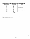

9-1-2
DC
TERMINAL
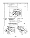
Check continuity between the DC terminals at the rear of the control panel using a circuit tester, under
the condition that the DC terminals is mounted
on the control panel. (See Fig.
9-1.)
w
When continuity between the DC terminals is confirmed with a wire connected across the terminals, and
is not confirmed
if
the wire
is
removed, the DC terminals are normal. (See Fig.
9-1.)
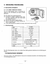
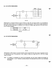
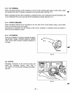
9-1-3
CIRCUIT
BREAKER
Check continuity between the two terminals
at
the rear side of the circuit breaker using a circuit tester
while it is mounted
on
the control panel.
If
continuity
is
confirmed when the breaker
is
ON,
and no continuity is confirmed when the breaker is
OFF,
the circuit breaker
is
normal.
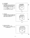
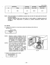
9-14
VOLTMETER
Check the voltmeter
if
it operates correctly by apply-
ing specified voltage. Voltmeters caunot be checked
with a circuit tester because its internal resistance
is
too large.
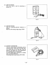
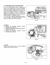
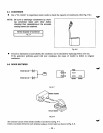
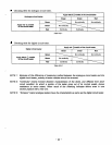
9-2 STATOR
Disengage connectors
on
the wires from stator and
check the resistance between wires with a
“Dr. Robin” or a circuit tester referring to the follow-
ing table.
AC
Voltmeter
Fig.
9-3
I
I
Fig.
9-4
-
27
-