9 - 38
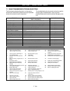
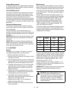
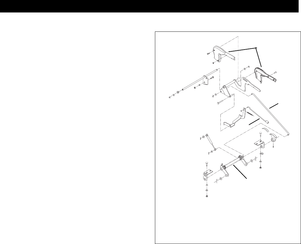
9.1 LIFT SYSTEM OVER VIEW
The lift system on the unit uses a spring assisted
system to take the weight of the attachment away from
the operator.
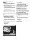
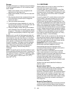
9.2 LIFT SYSTEM REMOVAL
1. With the mower attachment removed from the unit
the lift handle should be left in the up position.
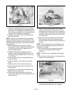
2. Remove the cotter pins on the mower lift link.
3. Remove the left center lift bracket support. Support
the lift assembly and remove the left bracket.
Remove the spring assembly from the unit.
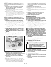
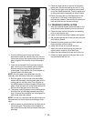
4. Removal of the upper lift assembly handle on the
rear deck of the unit will need to be removed.
5. Move the fuel tank forward to allow access to the
mounting hardware.
6. Remove the plastic handle covering on the lift
handle.
7. Release and remove the detent lever tension
spring.
8. Remove the pivot pin from the lift linkage and
remove detent lever from the linkage.
9. Remove the external ring from the ends of the lift
lever pivot and remove the washers and bushings.
10.Remove the carriage bolts and nuts holding the
pivot rod to the rear deck supports.
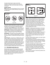
9.3 LIFT SYSTEM INSTALLATION
1. Insert the cross shaft and coil assembly into the
support bracket still in the unit and mount the left
with the hardware removed with it.
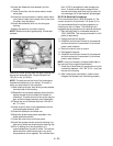
2. Insert the fuel line and wire harness into the J
clamp and bend closed.
3. Insert the lift rod into the lift arm cross shaft and
secure with washers and cotter pin.
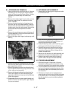
4. Reassemble the upper lift assembly into the rear
deck support and secure with the hardware
removed earlier.
5. Install the bushings and washers onto the rod ends
and secure with the external retaining rings.
6. Install the pivot pin into the lift linkage and attach
the detent lever tension spring.
7. Reinstall the plastic handle covering over the metal
lift handle subframe.
8. Attach the mower lift link and secure with the cotter
pin.
9. Check function and operation prior to installing the
mower attachment.
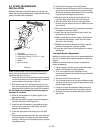
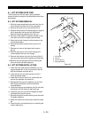
SECTION 9 - LIFT SYSTEM
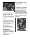
1. Lift Handle
2. Lift Link
3. Tension Spring
4. Spring Assembly
3
4
1
2
PT0111
Figure 46


