4 - 20
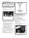
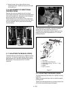
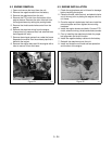
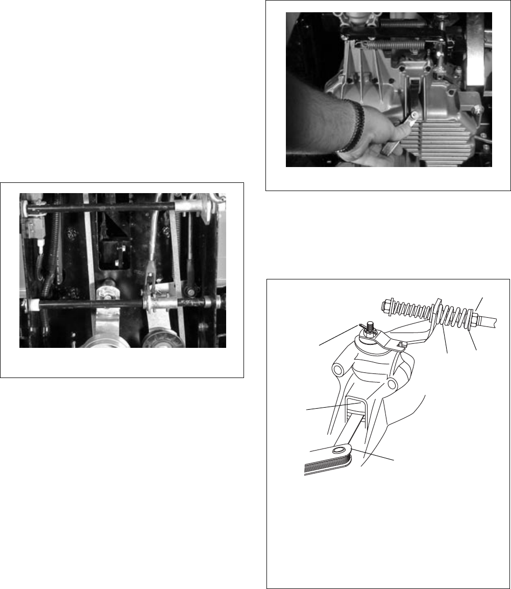
6. Adjust the ball joint to align with ball on the
transaxle shift arm. Attach the ball joint to the ball
on the shift arm.
4.16 ADJUSTMENT OF DIRECTIONAL
CONTROL PEDAL
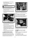
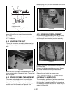
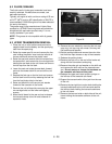
Remove the clevis pin holding the shift rod to the
control pedal cross shaft. Push the forward pedal down
and mark the pedal arm. Depress the rear directional
control pedal and mark the pedal arm.
Place the pedal arm in the center of the forward and
reverse marks and adjust the clevis to allow the clevis
pin to be installed. Hold in place with the hardware
removed earlier.
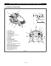
4.17 ADJUSTING THE BRAKE (HYDRO)
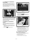
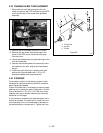
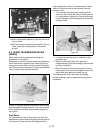
The brake was set at the factory for a specific running
clearance. To check for proper setting, place a feeler
gage between two of the disks (the brake will need to
be released). There should be 0.015" to 0.025"
clearance.
If the clearance is not correct, make the necessary
adjustment with the brake lever tension nut.
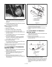
The brake arm compression spring in the front of the
brake arm should be compressed to 0.75" with the
parking brake set.
4.18 ADJUSTING THE BRAKE (GEAR)
The brake was set at the factory for a specific running
clearance.
Raise and support the rear of the unit with the wheels
off the ground.
Tighten the brake adjustment nut and then back off the
nut until the rear wheel drag is eliminated.
Figure 15
936-11
Figure 16
936-12
Figure 17
OT0840
1. Disc Brake
2. Castellated Nut w/Cotter Pin
3. Compression Spring- .78" OD x 1 " long
4. Feeler Gage
5. Washer
6. Nylon Lock Nut
1
2
3
4
5
6


