


7 - 36
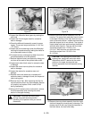
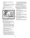
3. Push the shifting keys through the reverse
sprocket and push the neutral collar over the end
of the keys and pull the neutral collar and reverse
gear up against the shoulder of the shifter/brake
shaft.
4. Insert the countershaft into the smaller reverse
gear. Insert a thin thrust washer next to the gear
and then install the larger bevel towards the
reverse gear. Place another thin thrust washer on
the back side of the bevel gear.
NOTE:
As all the gears are placed back into the
assembly, each should be oiled prior to assembly.
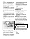
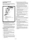
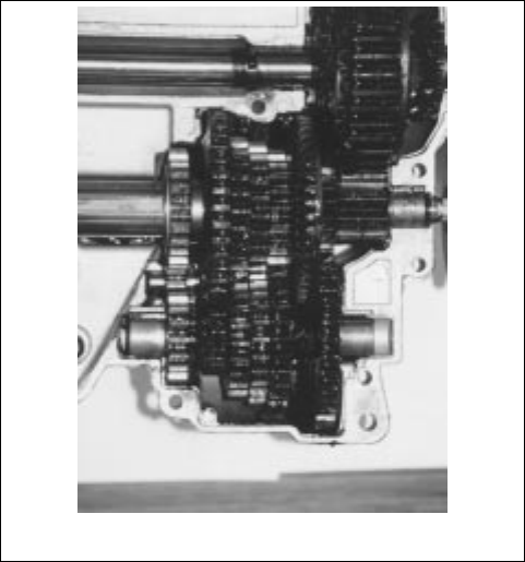
5. Build the gears on the counter shaft and shifter/
brake shaft alternately, meshing each gear with it’s
mating gear on the other shaft. The first gear on
the shifter/brake would be the largest of the shifting
gears. Place this gear next to the neutral collar with
the flat side of the gear next to the collar.
6. Then place a shifting washer onto the shifter/brake
shaft with the rounded edge towards the shifting
keys. Continue this procedure until all the gears on
both shafts have been added.
NOTE:
It is not only important that the gears match up
diameter-wise, but must match up according to thick-
ness.
7. Add the spacer to countershaft on the other side of
the reverse gear. Then place a thrust washer on
each end of the counter shaft and insert the bronze
bushings.
8. Place the large washer on the end of the shifter/
brake shaft, the bronze bushing and the "O" ring.
9. Place the spur gear onto the splines on the other
end of the shifter/brake shaft. The thin washer and
bushing conclude the assembly of these 2 shafts.
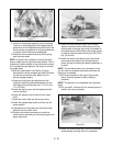
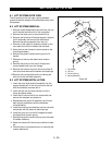
10.Place the output gear on the stepped end of the
output pinion. The shaft in the output pinion is
permanently pressed. Place the thrust washers on
each end and then the bronze bushings.
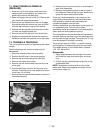
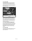
7.4 TRANSAXLE INSTALLATION
1. With the transaxle support plates mounted on the
axle, place the axle assembly into the unit frame.
2. Place the brake rod into the brake arm assembly
prior to mounting the axle.
3. Install all the axle mounting hardware and tighten.
4. Set the parking brake and install the main drive belt
onto the axle sheave.
5. Release the parking brake and check the belt
finger locations and belt routing.
6. Install the link ball joint onto the shift arm.
7. Attach the neutral switch wiring plug onto the
neutral switch, check for OK to start light.
8. Attach the rear tailboard onto the rear of the unit.
9. Check for proper operation and place the unit on
the ground and test the unit.
Figure 43