


Manual de Instrucciones de Operación y Piezas
Para Piezas de Repuestos, Llame al 1-877-278-2797
Sírvase proporcionar la suguiente información:
- Número de modelo
- Número de serie (si tiene)
- Descripción y número de repuesto como se muestra
en la lista de repuestos
Envíe su solicitud de repuestos a la siguiente direccion:
AquaPro Systems
101 Production Drive
Harrison, OH 45030 U.S.A.
3
2
1
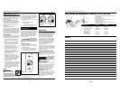
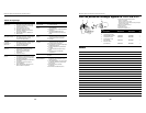
1 Juego de la bomba 69004-001 69005-001 1
2 Juego del sello del eje 21009-001 21009-001 1
3 Juego del motor 69000-001 69001-001 1
4 Tapa del cuerpo
de la bomba 28563-001 28564-001 1
5 Cesta filtrante
(no se muestra) 28565-001 28566-001 1
No. de
Ref. Descripción WIP100PRO WIP150PRO Ctd.
4
Notas
15 Sp
2
Operating Instructions and Parts Manual
Installation (Continued)
NOTE: Use an adhesive primer to
ensure adhesive joints are secure.
Suregard P-3000 has a purple tracer to
qualify in areas where codes specify a
primer must be used.
Consider climatic conditions when
applying adhesives. Atmospheric condi-
tions with high humidity will make the
adhesive action of certain glues less
effective. Follow the manufacturer’s
instructions.
THREADED CONNECTIONS
Use only Teflon
®
tape or equivalent on
threaded plumbing connections. Other
pipe compounds may damage threads.
Do not use silicone or petroleum based
compounds. Do not overtighten. Hand
tightening plus 1/2 turn is sufficient.
PUMP PLUMBING
Suction pipe should be as large or larger
than discharge pipe. Avoid using a suc-
tion pipe smaller than pump connection.
1. Keep the piping as straight and
short as possible, and of suitable
size.
2. Do not connect an elbow directly
into the pump inlet. A length of
straight pipe will allow proper entry
of the water to the pump.
3. Slope horizontal runs upward to the
pump to prevent trapping air.
4. Use independent piping supports to
alleviate strain on the pump.
5. Keep as much of the suction line as
possible below the water level to
reduce priming time.
6. Install valves and unions in the
pump suction and return lines to
facilitate servicing. Valves will throt-
tle the pump discharge. Valves are
also essential for pump mainte-
nance if the system is installed
below deck level.
7. Use a check valve in the suction pipe
for inground pumps at or below the
water level if the suction lift is more
than 5 feet or the dry suction is
more than 10 feet long. Keep the
valve in the suction line fully open
during operation.
WIRING
All
wiring must be performed
by a qualified electrician.
The pump must be installed
in compliance with all local codes and
the National Electrical Code.
!
WARNING
When motor installation is within 5 ft.
(1.5 m) of the pool’s interior walls, a
solid copper bonding conductor (mini-
mum size No. 8 AWG/8.4 mm
2
) should
be connected from the accessible wire
connector on the motor.
• to all metal parts of the swimming
pool
• to all electrical equipment
• to metal conduit
• to metal piping within 5 ft. (1.5 m)
of the pool’s interior walls
Refer to information on motor name-
plate for electrical service data. Install
motors with a fused disconnect switch
or dedicated circuit breaker. Be sure
wire size is sufficient for pump HP and
distance from power source. Install a
ground fault circuit interrupter for
maximum safety.
Disconnect, tag,
and lock out power
source before attempting to install, ser-
vice, relocate, or perform any mainte-
nance.
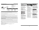
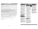
VOLTAGE SELECTOR
This pump is factory wired for 230 volts.
To change the voltage to 115 volts fol-
low the steps below:
1. Disconnect the pump from power.
2. Remove cover from back of motor
to find voltage selector (Figure 1a).
3. Pull selector knob out.
4. Rotate selector knob to correct volt-
age setting (Figure 1b).
!
DANGER
5. Push selector knob back in place.
6. Reinstall cover to back of motor.
Operation
Prime pump before attempting to oper-
ate. To prime pumps located above water
level, remove strainer cover, fill strainer
body with water then replace cover. If
pump and all piping is located below
water level, the pump will self prime.
After pump has been primed, open all
suction and discharge line valves and
energize motor. If no flow is observed
in five minutes, stop the motor and
reprime. If the pump fails to operate,
check for air leaks. Refer to trou-
bleshooting section.
After about 10 minutes of operation,
check the return fittings for air bubbles.
A continuous flow of air indicates leaks
in the suction line. Locate and correct
any leaks immediately.
CONTROLLING PUMP DISCHARGE
Keep the gate valve in the suction line
fully open during operation. To control
the discharge, use a valve in the return
line.
Do not retighten lid
during operation.
Do not operate
pump with closed
suction or discharge valve.
WATER CHEMISTRY
Proper and consistent use of chemicals
is necessary to manage a water system.
Chlorine is the most commonly used
chemical to provide clean, sanitary
water. Daily administration of dry or
liquid chlorine (calcium or sodium
hypochlorite) is essential.
IMPORTANT: Maintain the correct
level of acidity or alkalinity of the pool
water. Readings above pH 7.0 are alka-
line. A pH 7.0 is neutral. Readings
below pH 7.0 are acidic. A desirable
range is 7.2 to 7.4.
!
CAUTION
!
CAUTION
IMPORTANT: Use copper
conductors only.
L1
L2
LO
HI
Volt
Figure 1a
LO
LO
Volt
Volt
HI
HI
115 Volts
115 Volts
230 Volts
230 Volts
Volt
Volt
LO
LO
HI
HI
Figure 1b