


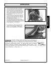
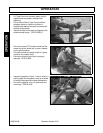

OPERATION
A96B 03/06 Operation Section 4-17
© 2006 Alamo Group Inc.
OPERATION
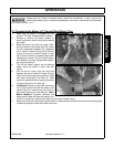
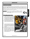
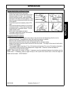
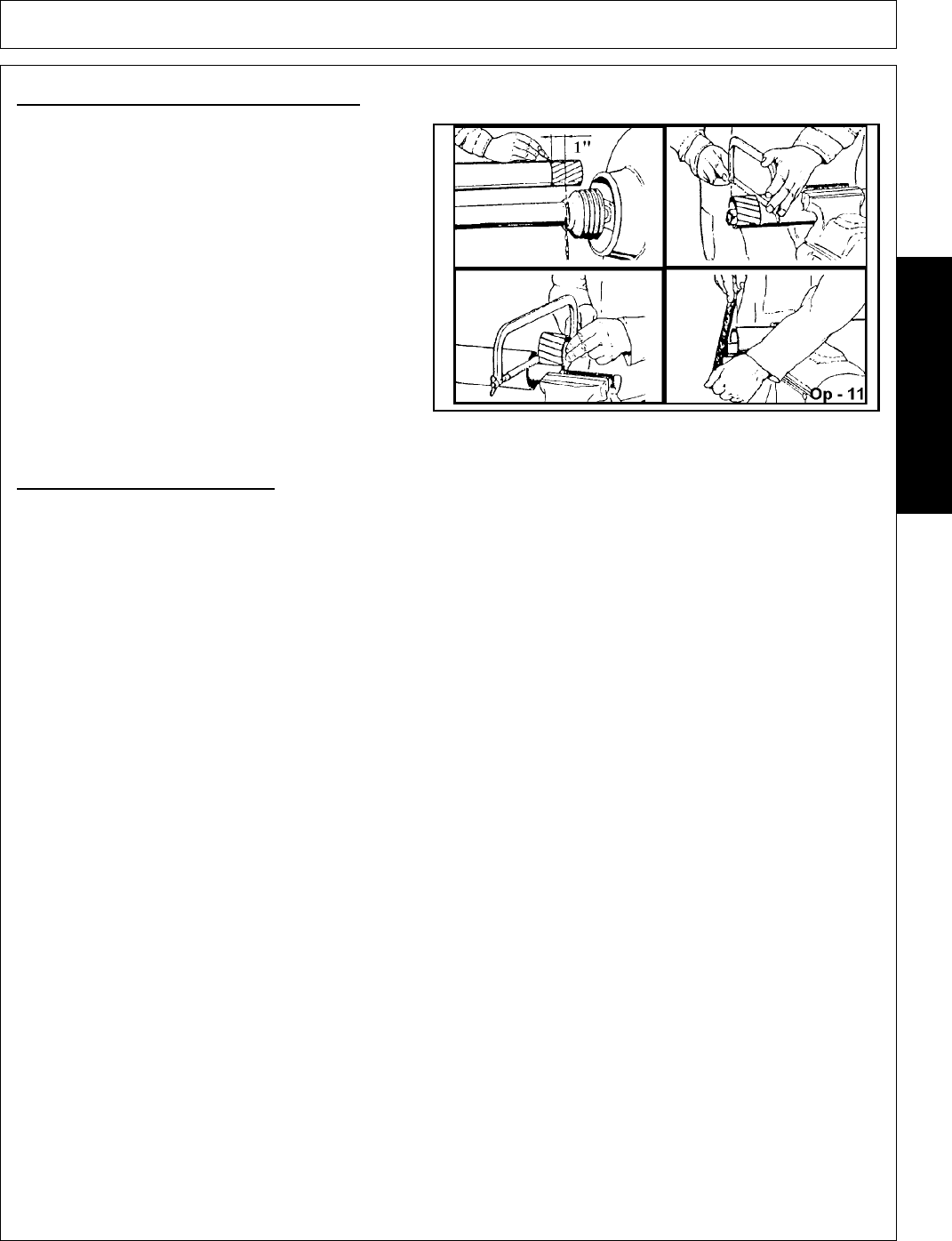
Shorten the driveline profiles as follows:
• Remove the driveline from the tractor.
• Position the mower (Lift and Semi-Mount Type -
Raise and lower/ Pull Type - Turn sharply) to
the point with the shortest distance between
the tractor PTO shaft and cutter gearbox. Shut
down the tractor and securely block the mower
in this position.
• Pull driveline apart and reattach yoke to PTO
shaft.
• Hold driveline sections parallel to one another
and measure back 1” from yoke of each shaft
and place mark on opposite section. Cut this
length off with a saw.
• Round off all sharp edges and debur.
• Thoroughly grease then reinstall the driveline.
• Recheck for proper operation.
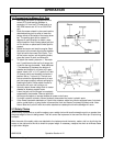
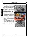
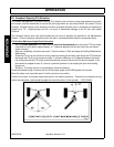
Engagement Check Procedure
• With the driveline attached, position the mower to the point where the telescoping driveline is at its
maximum extension. Completely shut down the tractor and secure in position.
• Mark the inner driveline shield 1/8” from the end of the outer shield.
• Disconnect the driveline from the tractor and separate the two driveline halves.
• Measure the distance from the mark to the end of the inner profile. This length is the amount the driveline
profiles were engaged.
• If the engaged length is less than 12” for a CV driveline and less than 6” for a non-CV driveline, the shaft is
considered too short and should be replaced with a longer shaft. Consult an authorized dealer to
purchase the required driveline length.
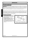
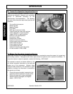
NOTE: When raising the mower, at least 1” clearance must be maintained between the driveline and the
mower deck. If necessary, place an upper lift stop on the 3-point hitch control lever to limit the height the
mower can be raised. OPS-R-0005-G