


Timing of Generated Signals Using the Agilent 81133A/81134A Pulse Generator
Agilent 81133A/81134A Pulse Generator User’s Guide, January 2005 77
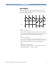
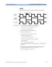
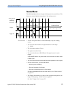
Clock
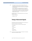
The following figure shows the typical timing for the clock signal.
Characteristics • Pulse periods are generated continuously where:
– Delay and deskew of all channels is zero.
– The duty cycle is fixed at 50%.
• The instrument mode is Pulse/Pattern.
• The pattern mode is Square.
• For the clock source, you can select from:
– Internal (YIG Oscillator)
– External signal at Clock Input
– External 10 MHz Reference at Clock Input
– Direct Internal
– Direct External at Clock Input
For more information about the clock sources, see “Clock Sources”
on page 73.
• The Trigger Out is generated with every clock pulse, but can be
optionally divided by any number in the range 1 ... 2
31
– 1.
See also “Trigger Out” on page 75.
Trigger Out
Output
Channel 1
Output
Channel 2
Freq. Divider = 2
Duty Cycle = 50 %