


Using the Agilent 81133A/81134A Pulse Generator Timing of Generated Signals
76 Agilent 81133A/81134A Pulse Generator User’s Guide, January 2005
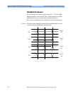
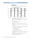
NOTE The trigger divider does not take the frequency divider of the
channels into account. For a frequency divider of n, n trigger pulses
are generated for each data packet, starting with the first edge of bit
0 of the data packet.
To get one trigger pulse per data packet when the channel divider
factor is not equal to 1, the trigger mode must set to Trigger on
pulse and the divider to n x X, where n is the frequency divider and
X is the data length. For example, if the data length = 32 bits and the
frequency divider of channel 1 = 2, the frequency divider of the
trigger output has to be 64.
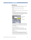
The trigger output can be enabled/disabled. The levels of the trigger
output can be set as:
• Low Level – High Level
• Amplitude – Offset
Timing of Generated Signals
The following sections provide information about the signals that can
be generated and shows the typical timings.
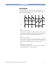
The instrument allows you to generate the following signals:
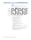
•Clock signals
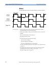
•Pulses
• Data patterns
•PRBS
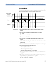
• Started bursts
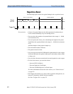
• Repetitive bursts
NOTE You can also set the frequency divider for all channels. The minimum
frequency must remain above 15 MHz.