


5-9
Troubleshooting
To check out the oscilloscope
5
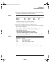
Disconnect the display ribbon cable from the system board. Then check
the signals on the system board listed in Table 5-2.
Table 5-2 Display Signals on the System Board – All Oscilloscopes
If the signals are good, replace the display assembly.
If the signals are not good, replace the system board.
6
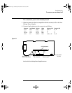
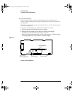
Disconnect the ribbon cable from the display board.
7 Check the low voltage power supply. Go to “To check the Low Voltage
Power Supply” on page 5-11.
If the voltages are within the test limits, replace the display assembly.
If the voltages are not within the test limits, follow these steps:
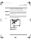
a Disconnect the power cord.
b Disconnect the ribbon cable from the power supply.
c Connect the dummy load to the power supply connector.
d Connect the power cord. Then measure the power supply voltages again.
See the new tolerances in Table 5-3.
Table 5-3
Low Voltage Power Supply Tolerances
If the voltages are within the test limits now, replace the system board.
If the voltages are still not within the test limits, replace the power supply.
Signal Name Frequency Pulse Width Voltage
J900 Pin 14 Hsync 19.72 kHz 3.0 ms 4.5 V
p-p
J900 Pin 13 Vsync 60.00 Hz 253.5 ms 4.5 V
p-p
Supply Voltage Tolerance
+5.1 V ±153 mV (+4.947 V to +5.253 V)
-5.2 V ±156 mV (-5.04 V to -5.36 V)
+15.75 V +1.260 V, -787 mV (+14.963 V to +17.010 V)
+3.3 V ±100 mV (+3.20 V to +3.40 V)
service.book Page 9 Wednesday, December 18, 2002 8:35 AM