


3-14
Testing Performance
To verify bandwidth
1
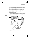
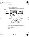
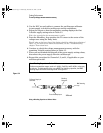
Connect the oscilloscope calibrator output through a 50Ω feedthrough
to the oscilloscope channel 1 input.
2 Set up the oscilloscope.
a Set the time base to 500 ns/div.
b Set the Volts/Div for channel 1 to 200 mV/div.
c Press the Acquire key, then press the Averaging softkey.
d Turn the Entry knob to set #Avgs to 8 averages.
3
Set the calibrator to “Level Sine” and OPR/STBY to “OPR”.
4 Set the calibrator for 1 MHz and six divisions of amplitude.
5 Press Autoscale on the oscilloscope.
6 Press the Quick Meas key, then press the Peak-Peak softkey.
Wait a few seconds for the measurement to settle (averaging is then complete).
View the Pk-Pk reading at the bottom of the display.
Record the reading: V
p-p
= _______ V.
7
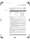
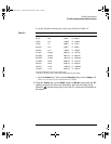
Change the frequency of the signal generator to the value shown below
for your instrument.
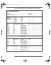
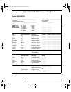
Table 3-7 Signal Generator Frequency Setting
8
Change the time base to 5 ns/div.
a Wait a few seconds for the measurement to settle.
b View the Pk-Pk reading at the bottom of the display.
c Record the reading: V
p-p
= ______ mV.
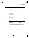
9
Calculate the response using this formula:
If the result is not ±3 dB, see the “Troubleshooting” chapter. Then return here.
10 Repeat this procedure (steps 1 to 9) for channel 2, 3, and 4, as applicable
to your oscilloscope model.
Proceed to the next step after you have completed the procedure for channels
2, 3, and 4, as applicable.
Selected Channel 54621A/21D 54622A/22D 54624A
Channel 1 60 MHz 100 MHz 100 MHz
Channel 2 60 MHz 100 MHz 100 MHz
Channel 3 ——100 MHz
Channel 4 ——100 MHz
20 10log
Step8Result
Step6Result
--------------------------------
⋅
service.book Page 14 Wednesday, December 18, 2002 8:35 AM