


3-9
Testing Performance
To verify digital channel threshold accuracy
7
Press the oscilloscope User softkey, then turn the Entry knob () on
the front panel
on the oscilloscope to set the threshold test settings as
shown in Table 3-3.
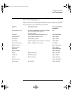
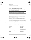
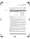
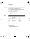
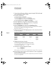
Table 3-3 Threshold Accuracy Voltage Test Settings
8
Do the following steps for each of the threshold voltage levels shown
in Table 3-3.
a Set the threshold voltage shown in the User softkey using the Entry knob on
the oscilloscope.
b Enter the corresponding DC offset voltage on the oscilloscope calibrator
front panel. Then use the multimeter to verify the voltage.
Digital channel activity indicators are displayed on the status line at the top
of the oscilloscope display. The activity indicators for D7-D0 should show all
of the channels at digital high levels.
c Use the knob on the oscilloscope calibrator to decrease the offset voltage,
in increments of 10 mV, until the activity indicators for digital channels
D7-D0 are all at digital low levels. Record the oscilloscope calibrator voltage
in the performance test record.
d Use the knob on the oscilloscope calibrator to increase the offset voltage,
in increments of 10 mV, until the activity indicators for digital channels
D7-D0 are all at digital high levels. Record the oscilloscope calibrator
voltage in the performance test record.
Before proceeding to the next step, make sure that you have recorded the
oscilloscope calibrator voltage levels for each of the threshold settings shown
in Table 3-3.
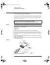
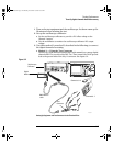
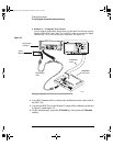
9
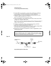
Use the 8-by-2 test connector or the Agilent 01660-63801 Test Fixture
to connect digital channels D15-D8 to the output of the oscilloscope
calibrator. Then connect the D15-D8 ground lead to the ground side of
the 8-by-2 connector.
10 Repeat this procedure for digital channels D15-D8 to verify threshold
accuracy and record the threshold levels in the Performance Test
Record.
Threshold voltage setting
(in oscilloscpe User softkey)
DC offset voltage setting
(on oscilloscope calibrator)
Limits
+5.00 V +5.250 V ±1 mV dc Lower limit = +4.750 V
Upper limit = +5.250 V
–5.00 V –4.750 V ±1 mV dc Lower limit = –5.250 V
Upper limit = –4.750 V
0.00 V +100m V ±1 mV dc Upper limt = +100 mV
Lower limit = –100 mV
service.book Page 9 Wednesday, December 18, 2002 8:35 AM