


3-12
Testing Performance
To verify voltage measurement accuracy
3
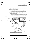
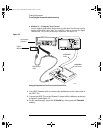
Use the BNC tee and cables to connect the oscilloscope calibrator
/power supply to both the oscilloscope and the multimeter.
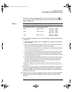
4 Adjust the output so that the multimeter reading displays the first
Volts/div supply setting value in Table 3-5.
Wait a few seconds for the measurement to settle.
5 Press the Y2 softkey, then position the Y2 cursor to the center of the
voltage trace using the Entry knob.
The ∆Y value on the lower line of the display should be within the test limits of
Table 3-5. If a result is not within the test limits, see the “Troubleshooting”
chapter. Then return here.
6
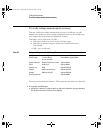
Continue to check the voltage measurement accuracy with the
remaining Volts/div setting values in Table 3-5.
7 When you are finished checking all of the power supply setting values,
disconnect the power supply from the oscilloscope.
8 Repeat this procedure for Channels 2, 3, and 4, if applicable on your
oscilloscope model.
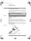
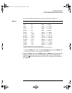
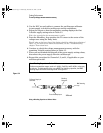
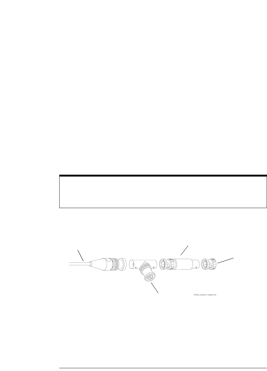
Figure 3-4
Using a Blocking Capacitor to Reduce Noise
Use a Blocking Capacitor to Reduce Noise
On the more sensitive ranges, such as 1 mV/div, 2 mV/div, and 5 mV/div, noise may
be a factor. To eliminate the noise, use a BNC Tee, blocking capacitor, and BNC
shorting cap to shunt the noise to ground. See figure 3-4.
To oscilloscope input
BNC shorting
cap
To Power Supply or
Calibrator
Blocking
Capacitor
service.book Page 12 Wednesday, December 18, 2002 8:35 AM