


1-11
General Information
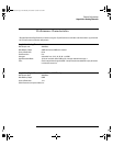
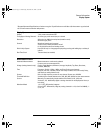
Vertical System: Analog Channels (continued)
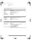
Vertical System: Analog Channels (continued)
ESD Tolerance ±2 kV
Noise Peak-to-Peak 2% full scale or 1 mV, whichever is greater
Common Mode Rejection Ratio 20 dB @ 50 MHz
DC Vertical Gain Accuracy*
1
±2.0% full scale
DC Vertical Offset Accuracy < 200 mV/div: ±0.1 div ±1.0 mV ±0.5% offset
≥200 mV/div: ±0.1 div ±1.0 mV ±1.5% offset value
Single Cursor Accuracy
1
±{DC Vertical Gain Accuracy + DC Vertical Offset
Accuracy + 0.2% full scale (~1/2 LSB) }
Example: For 50 mV signal, scope set to 10 mV/div (80 mV full scale), 5 mV offset,
accuracy = ±{2.0%(80mV) + 0.1 (10 mV) + 1.0 mV + 0.5% (5 mV) + 0.2%(80 mV)} = ± 3.78 mV
Dual Cursor Accuracy*
1
±{DC Vertical Gain Accuracy + 0.4% full scale (~1 LSB)}
Example: For 50 mV signal, scope set to 10 mV/div (80 mV full scale), 5 mV offset,
accuracy = ±{2.0%(80 mV) + 0.4%(80 mV)} = ±1.92 mV
1
1 mV/div is a magnification of 2 mV/div setting. For vertical accuracy calculations, use full scale of 16 mV for 1 mV/div sensitivity setting.
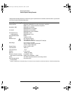
Vertical System: Digital Channels (54621D and 54622D only)
Number of Channels 16 Digital – labeled D15 – D0
Threshold Groupings Pod 1: D7 - D0
Pod 2: D15 - D8
Threshold Selections TTL, CMOS, ECL, user-definable (selectable by pod)
User-Defined Threshold Range ±8.0 V in 10 mV increments
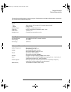
Maximum Input
Voltage
±40 V peak CAT I
Threshold Accuracy* ±(100 mV + 3% of threshold setting)
Input Dynamic Range ±10 V about threshold
Minimum Input Voltage Swing 500 mV peak-to-peak
Input Capacitance ~ 8 pF
Input Resistance 100 k
Ω ±2% at probe tip
Channel-to-Channel Skew 2 ns typical, 3 ns maximum
* Denotes Warranted Specifications, all others are typical. Specifications are valid after a 30-minute warm-up period and
±10 °C from firmware calibration temperature.
service.book Page 11 Wednesday, December 18, 2002 8:35 AM