


MOTOR SPECIFICATIONS
•1450 RPM
•380/415-3-50
•Solid base
•56 Frame
•Inherently protected
•Permanently lubricated
ball bearings
MAINTENANCE
FILTERS — Thefilters must be replaced as often asnecessary
to assure good air flow and filtering action.
EVAPORATORCOIL — Do not allow dirt to accumulate on the
evaporator coil or other parts of the evaporatorair circuit. Clean
as often as necessary to assure good system performance.
Use a brush, vacuum cleaner attachment or other suitable
means.
LUBRICATION — The bearings for the blower shaft and the
blower motors are permanently lubricated and should not re
-
quire additional lubricant.
DRAIN PAN — The drain pan should be inspected regularly
to assure proper drainage.
BELTS — Maintain belt tension to extend belt life. Replace
when signs of failure begin to appear.
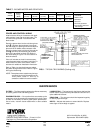
POWER AND CONTROL WIRING
Install electrical wiring in accordance with appli
-
cable national, local and municipal codes. The
unit should be grounded in accordance with
these codes.
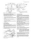
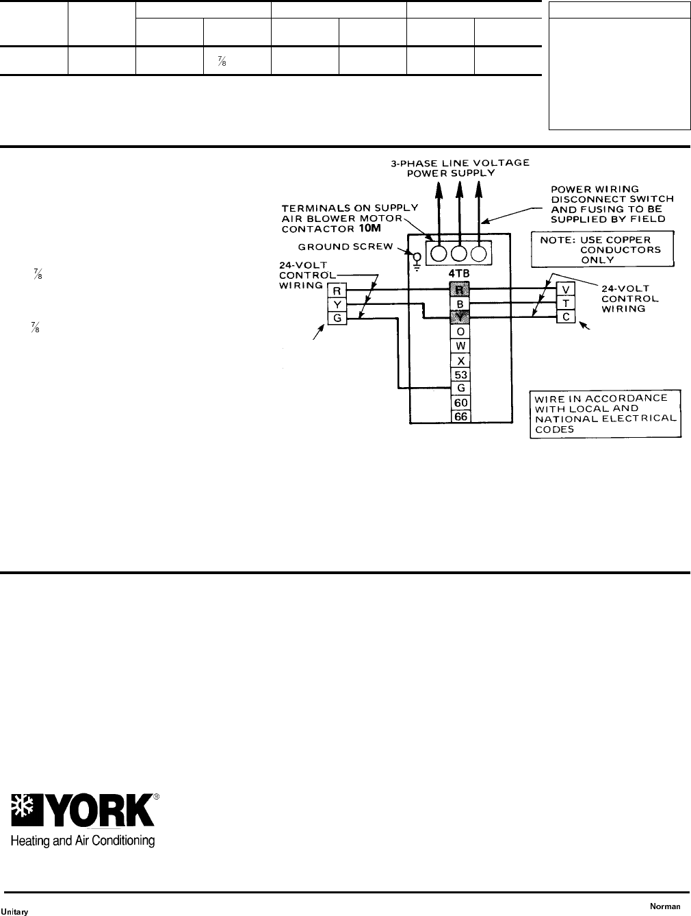
Route the power wires into the unit through one
of the
" (22.2mm) dia.knockouts in the panel
with the supply air opening and connect them to
the terminals on blower motor contactor 10M.
Route the control wires into the unit through the
other
" (22.2mm) dia.knockout and connect
them to the terminals on block 4TB. Refer to
the unit drawing in Figure 7 for the locations of
these knockouts.
If the unit includes an electric heat accessory,
route the power wires into heater control box in-
stead of the unit. Refer to the electric heat in-
structions for additional installation information.
Refer to Table 4 to size the disconnect switch,
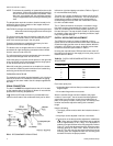
the power wiring and the fuses. Refer to Figure
8 for typical field wiring.
NOTE: Three phase motor rotation may be incor-
rect when the unit is first started up. Re
-
verse phase (leads L1 and L2) at
contactor to obtain the correct rotation.
FIG 8 - TYPICAL FIELD WIRING (Cooling only)
TERMINALSONBLOCK3TBOF
THE BLOWER UNIT
TERMINALS ON
1-STAGE COOLING
THERMOSTAT
2TH0870124
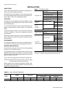
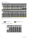
Motor
(HP/kW)
Blower
Range
(RPM)
Adjustable Motor Pulley Fixed Blower Pulley Belt
Pitch Dia
(In./mm)
Bore
(In./mm)
Pitch Dia.
(In./mm)
Bore
(In./mm)
Designation
Pitch Lg.
(In./mm)
3 / 2.2 615/800
3.4 - 4.4 / 86
- 112
/ 22.2
8.0 / 203 1 / 25 A54 55.3 / 1405
TABLE 7 - BLOWER MOTOR AND DRIVE DATA
Subject to change without notice. Printed in U.S.A
Copyright by York International Corporation
5005
York
Drive
035-12124-000 Rev. A (0501)
Supersedes: 550.39-N5YI (894)
Products
Group
OK
73069