


NOTE: To minimize the possibility of system failure due to dirt
and moisture,a filter-driermust be installedin eachliq
-
uid line as close to the evaporator as possible. Filter-
driers are not supplied with the evaporator blowers.
They are supplied with the matching condensing sec
-
tions.
The temperature required to make or break a brazed joint is
sufficiently high to cause oxidation of the copper unless an
inert atmosphere is provide.
CAUTION: Drynitrogen should flow througha brazed joint atall
times when heat is being applied and until the joint
has cooled.
The liquid, suction and drain connections inside the unit must
be piped to the outside. Refer to Unit Dimensions for loca
-
tions of the access openings in the unit panel.
Protective grommets are supplied by the factory for field
placement into these access openings.
The blower units are shipped with the coil section side pan
-
els suitable for right hand piping connections when viewed
from the return air side of the unit.
The refrigerant piping and the condensate drain connection
may be routed through either side of the unit.
If left hand piping is required, the two panels on the right side
of the coil section can be interchanged with the single panel
on the left hand side of the coil section.
When left hand piping connections are installed, the suction
line must be insulated to prevent moisture from condensing
and being carried into the blower section.
EXPANSION VALVE BULB
The expansion valve bulb must be fastened in a 4 o'clock po-
sition to the suction line outside the cabinet after the piping
connections have been made. Use the clamps supplied with
the valve.
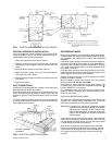
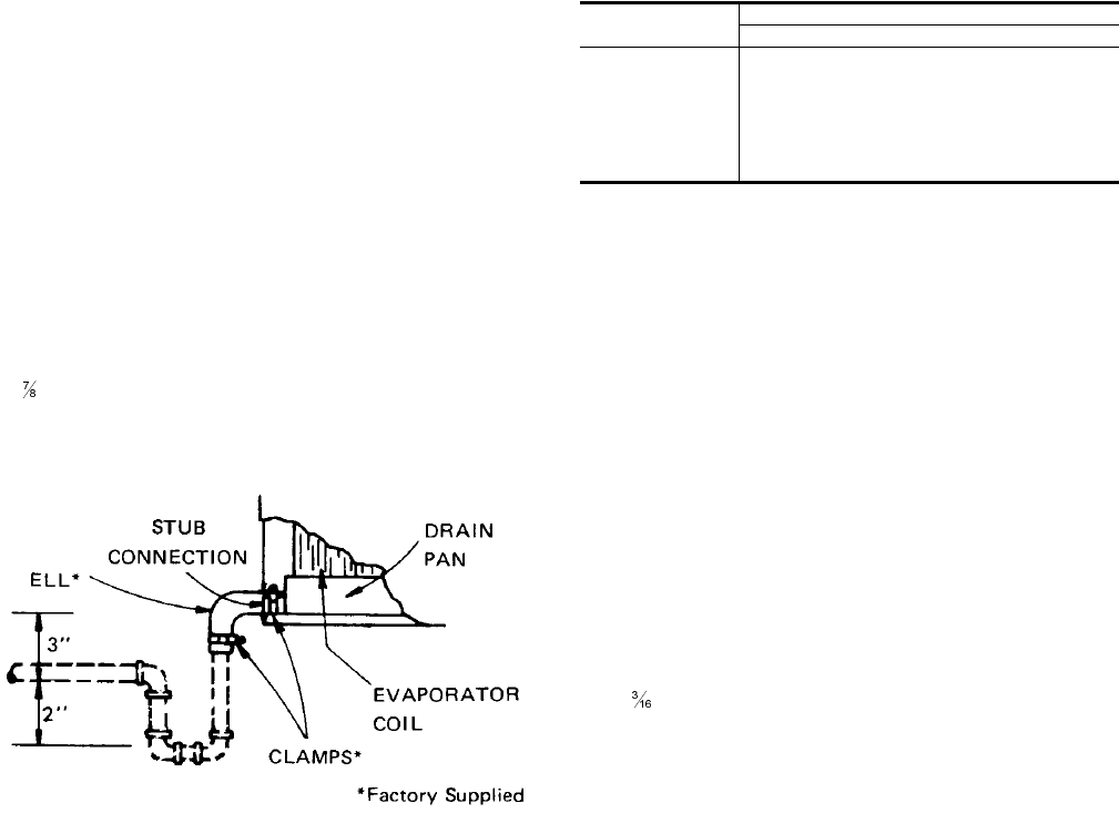
DRAIN CONNECTION
The drain line MUST be trapped because the coil is located
on the negative side of the supply air blower. It must also be
protected from freezing temperatures.
A
" (22.2mm) OD stub connection is provided within the
cabinet on both ends of the condensate drain pan for either
left hand or right hand piping connections. Refer to Figure 3
for recommended drain piping.
The drain line is usually located on the same end of the coil
section as the refrigerant connections. The line should be in
-
sulated where moisture drippage will be objectionable or
cause damage to the area. Seal the unused drain connec
-
tion with a suitable mastic.
The 3" (76mm) dimension must equal or exceed the nega
-
tive static pressure developed by the supply air blower. If it
does not, condensate will not drain properly and may over
-
flow the drain pan. The trap must be at least 2" (50mm) deep
to maintain a water seal under all operating conditions, espe
-
cially during blower start-up.
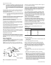
SUPPLY AIR BLOWER ADJUSTMENT
The RPM of the supply air blower will depend on the re
-
quired airflow, the unit accessories and the static resistances
of both the supply and the return air duct systems. With this
information, the RPM for the supply air blower can be deter
-
mined from the blower performance in Table 5
Knowing the required blower RPM and the blower motor HP,
the setting (turns open) for the supply air motor pulley can be
determined from Table 3..
Each motor pulley has:
1. A threaded barrel with two flats (or notched recesses) 180
degrees apart.
2. A movable flange with one set screw.
After the movable flange has been rotated to the proper
number of “turns open”, the set screw should be tightened
against the flat on the barrel to lock the movable flange in
place. If the pulley includes a locking collar, the locking collar
must be loosened to adjust the setting of the movable
flange.
Note the following:
1. The supply airflow must be within the limitations shown in
Table 2.
2. All pulleys can be adjusted in half-turn increments.
3. The tension on the belt should be adjusted for a deflection
of
" (5mm) per foot (305mm) of belt span with an applied
force of approximately 3 lbs (1.4kg). This adjustment is
made by moving the blower motor mounting plate. Refer to
Figure 4. Turning the adjustment bolt (B) moves the motor
mounting plate up or down. Note - Never loosen the two
nuts (C). Four hex nuts (A) have to be loosed to move the
mounting plate and retightened after the mounting plate
has been moved to the proper position.
4 Unitary Products Group
035-12124-000 Rev. A (0501)
FIG 3 - RECOMMENDED DRAIN PIPING
(76)
(50)
TURNS OPEN*
BLOWER DRIVE RANGE (RPM)
615-800
5 615
4 652
3 689
2 726
1 763
0 800
* Pulleys can be adjusted in half-turn increments.
TABLE 3 - SUPPLY AIR BLOWER MOTOR PULLEY
ADJUSTMENT