


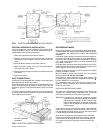
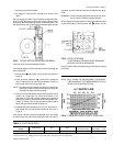


VERTICAL/HORIZONTAL INSTALLATION
The unit is shipped for vertical installation with a vertical air dis
-
charge as shown in Figure 1, but may be converted to other ar
-
rangements per the following instructions.
1. Remove the panels from the blower section.
2. Remove the four Phillips machine bolts that hold the coil
and blower sections together. A bolt is located near each
corner.
3. Move the blower section to the proper location.
4. Attach the blower section to the coil section with the ma-
chine bolts removed in Step 2.
5. Beforereplacing the panel, see Duct Connection and Drain
Connection.
6. Replace the panels.
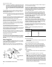
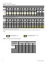
DUCT CONNECTIONS
All ducts should be designed and installed in accordance with
applicable national and/or local codes.
Ducts should be sized no smaller than the duct flanges on the
unit or the accessory electric heater (if used). Refer to the unit
dimensions (Figure 7) and the heater detail (Figure 2) for these
sizes.
The field installed air plenum and return air grille accessories
should be used in place of ductwork only when a free blow/free
return application is practical.
REFRIGERANT MAINS
Many service problems can be avoided by taking adequate pre
-
cautions to provide an internallyclean and dry system, and by us
-
ing procedures and materials that conform with established
standards.
Hard drawn copper tubing should be used where no apprecia-
ble amount of bending around pipes or other obstructions in
necessary. Use long radius ells wherever possible. If soft cop-
per is used, care should be taken to avoid sharp bends which
may cause a restriction.
Pack fiber glass insulation and a sealing material such as Per-
magum around refrigerant lines where they penetrate a wall to
reduce vibration and to retain some flexibility.
Support all refrigerant lines at minimum intervals with suitable
hangers, brackets or clamps.
Braze all copper to copper joints witH Sil-Fos 5 or equivalent
brazing material. Do not use soft solder.
Never braze or solder liquid and suction lines together. The
complete suction line should be insulated with no less the
"
(12mm) ARMAFLEX or equivalent.
If it is desirable to tape or wire the liquid and suction lines to
-
gether for support purposes, they must be completely insu
-
lated from each other.
INSTALLING REFRIGERANT MAINS
The units are evacuated and dehydrated at the factory and
shipped with a holding charge of Refrigerant-22. The suction
and liquid connections are sealed with copper disks.
WARNING: Provisions for recovering refrigerant releases
must be available during all phases of installation,
leak testing and charging. Do NOT release refrig
-
erant into the atmosphere. A Schrader valve is pro
-
vided on the coil header for recovering refrigerant
holding charge.
If the unit has already lost its holding charge, it should be leak
tested and the necessary repairs should be made. If the unit
has maintained its holding charge, you can assume that it has
no leaks and proceed with the installation.
Make sure the refrigerant in the lines has been recovered,
then drill a small hole through the discs to prevent any inter
-
nal pressure from blowing them off and to allow the flow of
dry nitrogen through the connections when unbrazing the
closures.
Unitary Products Group 3
035-12124-000 Rev. A (0501)
FIG 1 - VERTICAL AND HORIZONTAL APPLICATION
FIG. 2 - ELECTRIC HEATER ACCESSORY
(489)
(565)
(25)