


LIMITATIONS
These unitsmust be installedin accordance with applicable na
-
tional, local and municipal safety codes.
If components are to be added to a unit to meet local codes,
they are to be installed at the dealer's and/or the customer's ex
-
pense. Refer to Table 2 for Unit Application Data.
LOCATION
This blower unit is not designed for outdoor installation. It must
be located within the building structure, either inside or outside
the conditioned space.
The unit should be located as close to the condensing unit as
practical and positioned to minimize bends in the refrigerant
piping.
Units being installed vertically or horizontally can be set directly
on a floor or platform, or they can be supported by metal or
wooden beams.
Units being installed horizontally can also be suspended from
above. Refer to the suspension accessory instruction installa
-
tion procedures.
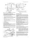
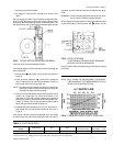
CLEARANCES
The clearances listed on the unit dimension drawing (Figure 7)
are required for the proper service and operation of the unit.
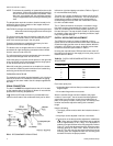
RIGGING AND HANDLING
Be careful when movingthe unit. Do not remove any packaging
until the unit is near its final location.
The packaging consists of a bottom wooden skid that can be
lifted with a fork truck from any direction, a clear heavy mil bag
that covers the entire unit, and strapping that secures the clear
bag to the bottom of the skid.
These units can be rigged with slings under the bottom skid.
CAUTION: Spreader bars should be used to prevent slings
from crushing the unit panels and frame.
Before rigging any unit, determine its weight from Table 1. Bef
-
ore rigging a unit for horizontal installation, make sure that its
weight will be distributed equally.
2 Unitary Products Group
035-12124-000 Rev. A (0501)I
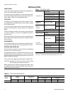
Evaporator Coil
Rows Deep 4
Rows High 26
Finned Length (in./mm) 54.5/1384
Fin/Inch 13
Tube O.D. (in./mm) 3/8/9.6
Face Area (Ft
.2
/m
2
) 12.4/1.15
Centrifugal
Blower
1
Wheel Dia. x Width
inches 18 x 18
mm 457 x 457
Filters
2
(6 Req'd)
Size
inches 20 x 20 x1
mm
508 x 508
x 25
Face Area (Ft.
2
/m
2
) 16.7/1.5
Operating Charge ( Refrigerant 22) (Lbs/Kg) 5.5/2.5
Weight (Lbs/Kg)
Shipping 480/218
Operating 440/200
Accessory
Weights(Lbs/Kg)
Electric Heaters
10 kW 63/28.5
16 kW 66/29.9
26 kW 71/32.2
36 kW 74/33.5
Supply Air Plenum 144/65
Base 65/29
Return Air Grille 19/9
Horizontal Suspension 68/31
Steam Coil 149/68
Hot Water Coil 135/61
1
Refer to data in Table 7 for complete motor specifications.
2
Filters are throwaway type.Two inch (50mm) filters may be used, if requiredby
removing the 1" (25mm) filter retaining angles provided in the filter rack.
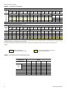
Table 1 - PHYSICAL DATA
Power
Supply
Voltage
Variation*
Supply Air Range
CFM/m
3
s
Entering Air Temperature, °F(°C)
Cooling-db/wb Heating-db
Min. Max. Min. Max. Min. Max. Min. Max.
380/415-3-50 342 457 4800/2.26 7200/3.40 68/57 (20/14) 86/72 (30/22) - 77 (25)
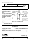
TABLE 2 - UNIT APPLICATION DATA
*Utilization Range “A” in accordance with ARI Standard 110.
INSTALLATION