


4. All pulleys are factory aligned.
5. All supply air motor pulleys are factory set at two “turns
open.”
After the supply air blower motor is operating, adjust the resis
-
tances in both the supply and the return duct systems to bal
-
ance the air distribution throughout the conditioned space. The
job specifications may require that this balancing be done by
someone other than the equipment installer.
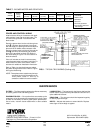
To check the supply air airflow after the the initial balancing has
been completed:
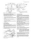
1. Drill two holes
" (8mm) dia. in the side panel as shown in
Figure 5.
2. Insert at least 8" (200mm) of
" (6.3mm) O.D. tubing into
each of these holes for sufficient penetration into the air
flow on both sides of the evaporator coil.
NOTE: The tubes must be inserted and held in a position per
-
pendicular to the air flow so that velocity pressure will
not affect the static pressure reading.
3. Using an inclined manometer, determine the pressure drop
across a dry evaporator coil. Since the moisture on an
evaporator coil may vary greatly, measuring the pressure
drop across a wet coil under field conditions would be inac
-
curate. To assure a dry coil, the refrigerant system should
be de-energized while the test is being run.
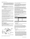
4. Knowing the pressure drop across a dry coil, the actual air
-
flow through the unit can be determined from the curve in
Figure 6.
If the airflow is above or below the specified valve, the supply
air motor pulley may have to be readjusted. After one hour of
operation, check the belt and pulleys for tightness and align
-
ment.
WARNING: Failure to properly adjust the total system air quan
-
tity can result in extensive blower damage.
After readings have been obtained, remove the tubes and seal
up the drilled holes in the side panel with
" (8mm) dia. dot
plugs (P/N029-13880) available through normalparts ordering
procedure.
Unitary Products Group 5
035-12124-000 Rev. A (0501)I
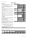
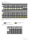
Blower Motor
HP/kW
Power Supply FLA LRA
Maximum
Fuse Size* Amps
Maximum
Wire Length* * Ft.(m)
3 / 2.2 380/415-3-50 5.2 37.0 10 400 (122)
* Dual element, time delay fuses.
** Based on three 60° C, 14 AWG, insulated copper conductors in steel conduit and a 3% voltage drop.
TABLE 4 - ELECTRICAL DATA
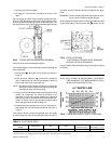
NOTE; SHUT DOWN THE REFRIGERANT SYSTEM BEF-
ORE TAKING ANY TEST MEASUREMENTS TO AS-
SURE A DRY EVAPORATOR COIL
FIG 4 - TYPICAL MOTOR MOUNTING ASSEMBLY
FIG 5 - HOLE LOCATIONS
(559)
(8)
(8)
(254)
(457
TO DETERMINE PRESSURE DROP READINGS
ACROSS THE DRY EVAPORATOR
FIG 6 - PRESSURE DROP VS SUPPLY AIRFLOW