


Unitary Products Group 7
035-12124-000 Rev. A (0501)
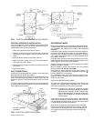
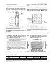
FIG 7 - UNIT DIMENSIONS AND CLEARANCES
UNIT
ACCESSORIES
•ELECTRIC HEATER
Add 15" (381mm) to Unit Height when using 10, 16, 26 or 36kW Heater
•SUPPLY AIR PLENUM
Add 27" (686mm) to Unit Height when used
•BASE
Add 24" (610mm) to Unit Height when used
MINIMUM CLEARANCES (in./mm)
Side with RETURN AIR opening - 24 / 610
Side with SUPPLY AIR opening - 24 / 610
1
Side with PIPING CONNECTIONS - 61 / 1549
2
Side opposite PIPING CONNECTIONS - 26 / 660
3
Bottom -
4
NOTES:
1
Overall dimension of the unit will vary if an electric heater, a supply air plenum or a base is used.
2
This dimension is required for removal of the DX coil. Only 26" (660mm) is required for normal serv
-
icing.
3
If the DX coil has to be removed, this dimension is required to loosen screws that secure the coil to
the unit frame. This dimension will also be required for blower motor access if the piping
connections are made on the opposite side of the unit.
4
Allow enough clearance to trap the condensate drain line.
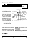
All dimensions are in millimeters and inches. They are sub-
ject to change without notice. Certified dimensions will be
provided upon request.