


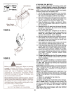

LIGHT SWITCH
The head lamps are operated by pushing the light
switch located on the dashboard. The head lamps will
only operate when the engine is running. See figure 8.
AMMETER
The ammeter registers the rate of battery charge or
discharge. The ammeter will register on the discharg-
ing side with starting the engine. It should register on
the opposite side (charging) when the engine is run-
ning in the fast position until the battery is completely
charged. With a fully charged battery or with the engine
idling, the ammeter will not show a charge. See figure 8.
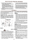
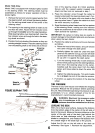
HYDROSTATIC CONTROL LEVER
The hydrostatic control lever is located on top of the
fender on the left side of the tractor. This single con-
trollever, connected to the hydrostatic transmission,
controls both the speed and direction of the tractor. In-
finite speed control is achieved by moving the control
lever forward or backward. The farther forward or
backward you move the control lever, the faster you
will travel. Pulling the control lever into neutral (N) area
will stop the tractor. See figure 9.
IGNITION SWITCH
The ignition switch is located on the dashboard. Turn
the key to the START position to start the engine. When
the engine is running, leave the key in the ON posi-
tion. To stop the engine, turn the key to the OFF posi-
tion. See figure 8.
A WARNING: Remove the key from the trac-
tor when the tractor is not in use to pre-
vent accidental starting.
THROTTLE CONTROL
The throttle control is located on the left side of the
dashboard and is used to regulate the engine speed.
See figure 8. The engine should be operated from 3/4
to full throttle (FAST) when operating any equipment
that uses the tractor engine as a source of power such
as the mowing deck, snow thrower or rotary tiller.
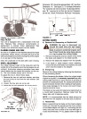
CHOKE CONTROL
The choke control is located on the right side of the
dashboard and is operated manually. Details for the
choke operation are covered in the separate engine
manual packed with your unit. See figure 8.
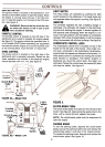
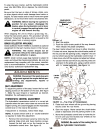
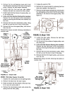
Lift
Lever
Light
Switch
Control I -
Clutch-Brake
Pedal I I
~
Ignition
Switch
FIGURE 8A.-Model 704F
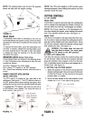
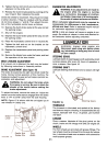
~Or-
Light
Switch
Lift
FIGURE 9.
Throttle
Control,j
Clutch-Brak~l1'-.. fill
Pedal! II Y
~ I <81
CLUTCH-BRAKE PEDAL
The clutch-brake pedal is located on the left side of thetractor.
See figure 8. Depressing the pedal returns the
drive unit to neutral (N) and applies the brake.
NOTE: The clutch-brake pedal must be depressed to
start the engine.
~
PARKING BRAKE
To set the parking brake, depress the clutch-brakepedal,
pull up the parking brake knob and release the
clutch-brake pedal. It will stay in the raised position.
To release the parking brake, depress and release the
clutch-brake pedal. See figure 10.
.
h 1--1
~" SWltC.. PTO
~Switch ~
.--~
FIGURE 8B.-Model 734F
"7