


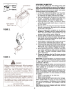


Model 734G Only:
Model 734G is equipped with indicator lights, located
in the steering wheel. The steering wheel must beassembled
as follows for proper operation of the in-dicator
lights.
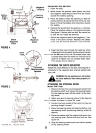
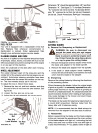
1. Remove the hex lock nut and cupped washer from
the steering shaft, and remove the steering bellow.
Pry the sterring wheel insert off the center of the
steering wheel.
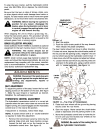
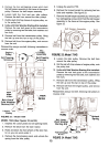
2. The opening in the steering bellow is wider at one
end than the other. Route the five indicator wires
up through the smaller end of the steering bellow.
Slide steering bellow over steering shaft. Insert the
five indicator wires up through the slot in the steer-
ing wheel as shown.
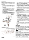
3. Position the front wheels of the tractor so they are
pointing straight forward. Place the steering wheel
over the steering shaft so the wires are at the bot-
Oil pro Clutch
r ' .r
~
Steering
sert
ite
~ "
~ed I
BI.Ck~
Brown
f?4S reen Hex Lock Nut;:?~~~~~ ~
Washer\\'
J
Steering
Bellow
FIGURE 68.
Model 734G
~
tom of the steering wheel (6 o'clock position).
Secure with the cupped washer (cupped side
down) and hex lock nut removed in step 1.
4. Place the indicator wires through the cable tie
located underneath the steering wheel insert. Con-
nect the wires to the same color wire leads in the
steering wheel insert. Tighten the cable tie to hold
the wires securely in position.
5. Snap the steering wheel insert over the four spokes
of the steering wheel, making sure the indicator
lights are positioned at the bottom of the steering
insert (toward the operator).
IMPORT ANT: Be certain to follow step six exactly to
prevent damage to the indicator lights and wire harness
when using the lawn tractor.
6. Position the cable tie and secure the wire harness
as follows.
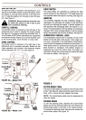
a. Raise the hood of the tractor, and pull excess
wire down through the dash panel.
b. Partially tighten the cable tie under the dash
panel so the cable tie is snug, but can still slide
up and down the wire harness. Slide the cable
tie up until it is against the dash panel.
c. Turn the steering wheel fully in both directions
(wires will be pulled up into the steering bellow),
then return the steering wheel to the center.
Carefully pull the wires down from the dash
panel, and move cable tie down the wires 1/4
inch.
d. Tighten the cable tie securely. Trim end of cable
tie so at least one inch of the cable tie remains.
7. Pull bellow up against the bottom of the steering
wheel.
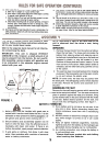
TIRE PRESSURE
The tires on your unit may be over-inflated for shippingpurposes.
Reduce the tire pressure before operating
the unit. Recommended operating tire pressure is ap-
proximately 12 p.s.i. (check sidewall of tire for tire
manufacturer's recommended pressure).
A WARNING: Maximum tire pressure under
any circumstances is 30 p.s.i. Equal tire
pressure should be maintained on all tires.
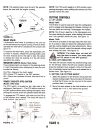
LEVELING THE DECK
With unit on hard, level surface, measure the distance
from the bottom edge of the center of the left side of
deck to the ground. Measure the same distance on the
center of the right side of the deck Oust behind the
chute area on side discharge units). Or, place the
blades in a straight line, and measure the distance fromthe
outside edge of the blade tips to the ground.
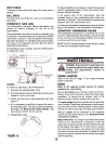
Adjust the lift link on the left side of the deck asnecessary.
See figure 7. Recheck the adjustment.
/'
FIGURE 7.
6