


CARBURETOR ADJUSTMENTS
A WARNING: If any adjustments are made to
the engine while the engine is running
(e.g. carburetor), disengage all clutches
and blades. Keep clear of all moving parts.
Be careful of heated surfaces and muffler.
Minor carburetor adjustments may be required to
compensate for differences in fuel, temperature,
altitude and load. Refer to separate engine manual
for carburetor adjustment information.
NOTE: A dirty air cleaner will cause an engine to runrough.
Be certain air cleaner is clean and attached to
the carburetor before adjusting carburetor.
LUBRICA TION
WARNING: Always stop engine and
disconnect spark plug wire before clean-
ing, lubricating or doing any kind of work
on lawn tractor.
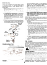
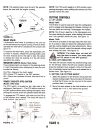
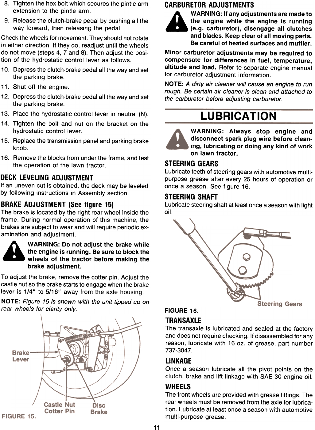
STEERING GEARS
Lubricate teeth of steering gears with automotive multi-
purpose grease after every 25 hours of operation or
once a season. See figure 16.
STEERING SHAFT
Lubricate steering shaft at least once a season with lightoil.
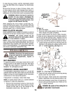
8. Tighten the hex bolt which secures the pintle arm
extension to the pintle arm.
9. Release the clutch-brake pedal by pushing all the
way forward, then releasing the pedal.
Check the wheels for movement. They should not rotate
in either direction. If they do, readjust until the wheels
do not move (steps 4, 7 and 8). Then adjust the posi-
tion of the hydrostatic control lever as follows.
10. Depress the clutch-brake pedal all the way and set
the parking brake.
11. Shut off the engine.
12. Depress the clutch-brake pedal all the way and set
the parking brake.
13. Place the hydrostatic control lever in neutral (N).
14. Tighten the bolt and nut on the bracket on the
hydrostatic control lever.
15. Replace the transmission panel and parking brake
knob.
16. Remove the blocks from under the frame, and test
the operation of the lawn tractor.
DECK LEVELING ADJUSTMENT
If an uneven cut is obtained, the deck may be leveled
by following instructions in Assembly section.
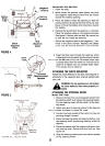
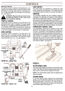
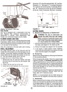
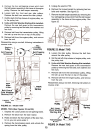
BRAKE ADJUSTMENT (See figure 15)
The brake is located by the right rear wheel inside the
frame. During normal operation of this machine, the
brakes are subject to wear and will require periodic ex-
amination and adjustment.
A WARNING: Do not adjust the brake while
the engine is running. Be sure to block the
wheels of the tractor before making the
brake adjustment.
To adjust the brake, remove the cotter pin. Adjust the
castle nut so the brake starts to engage when the brake
lever is 1/4" to 5/16" away from the axle housing.
NOTE: Figure 15 is shown with the unit tipped up on
rear wheels for clarity only.
FIGURE 16.
TRANSAXLE
The transaxle is lubricated and sealed at the factory
and does not require checking. If disassembled for any
reason, lubricate with 16 oz. of grease, part number
737-3047.
LINKAGE
Once a season lubricate all the pivot points on the
clutch, brake and lift linkage with SAE 30 engine oil.
WHEELS
The front wheels are provided with grease fittings. The
rear wheels must be removed from the axle for lubrica-
tion. Lubricate at least once a season with automotive
multi-purpose grease.
11