


-=
j,
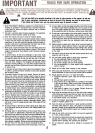
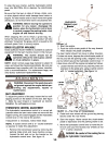
Negative
Terminal
/~
""
Battery
Drain
jTube-
/ Positive
0\ Terminal
J'r
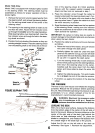
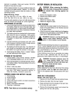
INSTALLING THE BATTERY
1. Raise the seat.
2. Make certain the positive cable (heavy red wire)
and negative cable (heavy black wire) are routed
outside the battery opening.
3. Place the battery inside the opening so that the
positive terminal is toward the front of the unit. See
figure 3. Route the battery drain tube down beside
the battery.
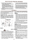
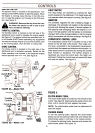
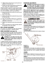
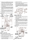
4. Remove the hex bolt from the positive (+) terminal.
Place the positive cable on the positive terminal.~See
figure 4. Secure with hex bolt. Be careful not
to lose the nut inside the terminal.
5. Secure the negative cable to the negative (-) ter-
minal in the same manner. Replace the battery
cover over the positive terminal. Lower the seat.
-,'
Black Red
(Negative) (Positive)
Cable Cable
FIGURE 4.
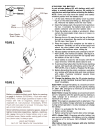
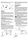
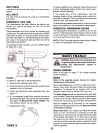
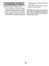
6. Insert the drain tube through the cable tie which
is attached to the transaxle reinforcement bracket
.on the left side of the unit. Be certain drain tube
is routed away from the wheel rim. Pull on end of
cable tie to tighten (do not collapse drain tube).
Trim excess end of cable tie.
Drain/""'- l
TUbeV I
r-~
Transaxle
Cable Reinforcement
Tie Bracket
ol
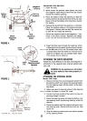
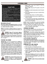
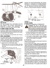
ATTACHING THE CHUTE DEFLECTOR
Attach the chute deflector to the deck, following the in-
structions in the separate deck manual packed with
your unit.
,~
1A
WARNING: Do not operate your unit unless
the chute deflector has been properly in-
stalled.
'":7-"
FIGURE 5.
ATTACHING THE STEERING WHEEL
Model 704F Only:
1. Remove the hex lock nut and cupped washer from
the steering shaft, and remove the steering bellow.
Pry the steering insert off the center of the steer-
ing wheel.
2. Attach one end of steering bellow to the steering
~ wheel as shown in figure 6A, inset.
3. Position the front wheels of the tractor so they are
pointing straight forward.
4. Place the steering wheel and steering bellow over
the steering shaft, positioning steering wheel as
desired.
5. Place the washer with the cupped side down over
the steering shaft. Secure with hex lock nut. See
figure 6A.
6. Snap the steering wheel insert over the four spokes
of the steering wheel.
5