


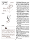
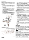
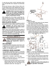

I'OiI
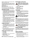
Hydrostatic
Control Lever
~~acket
~
~.~.
Loosen
FIGURE 13.
2. Start the engine.
3. Push the clutch-brake pedal all the way forward.
Then release the pedal completely.
The lawn tractor should not move in either direction.
If it does not move, depress the clutch-brake pedal all
the way and set the parking brake, retighten the bolt
and nut which secure the hydrostatic control lever. If
it does move, shut off the engine and adjust as follows.
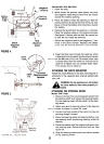
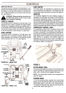
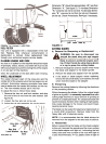
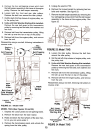
4. Loosen the hex bolt which secures the pintle arm
extension to the pintle arm, using a rachet wrench
with '/2" socket extension. See figure 14.
-~~ ~rr~'
To stop the lawn tractor, pull the hydrostatic control
lever into NEUTRAL (N) or depress the clutch-brake
pedal.
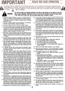
Be sure that the lawn is clear of stones, sticks, wire,
or other objects which could damage lawn tractor or
engine. For best results and to insure more even grass
distribution, do not mow when lawn is excessively wet.
A WARNING: Before leaving the operator's
position for any reason, disengage the
blades, place the hydrostatic control lever
in neutral, engage the parking brake, shut
engine off and remove the key.
When stopping the unit to empty a grass bag, etc.,
follow the instructions above. This procedure will also
eliminate "browning" the grass, which is caused by hot
exhaust gases from a running engine.
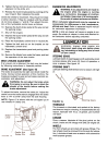
GRASS COLLECTOR AVAILABLE
Grass Collector Model 190063 is available as optional
equipment for the lawn tractors shown in this manual.
A WARNING: The mower should not be
operated without the entire grass catcher
or chute deflector in place.
NOTE: Under normal usage bag material is subject to
wear, and should be checked periodically. Be sure any
replacement bag complies with the mower manufac-
turer's recommendations. For replacement bags, use
only factory authorized replacement bag.
,I
r~wl
Pintle
Arm
WARNING: Disconnect the spark plug wire
and ground against the engine before per-
forming any adjustments, repairs or
maintenance.
~
~
~'"
~
I
/,
C
~J\)'J= Pintle Arm ~~'-1:.n
Extension \Y ~ ,
FIGURE 14.-Top View of Transmission
5. Raise both rear wheels off the ground by placing
blocks under the rear frame.
6. Start the engine. Make certain the clutch-brake
pedal is depressed and the parking brake is set.
7. Move the hydrostatic control lever to move the pin-
tie arm until you find neutral (rear wheels do not
rotate in either direction).
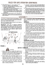
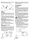
SEAT ADJUSTMENT
To adjust the position of the seat, loosen the four self-
tapping screws on the bottom of the seat. See figure
1. Slide the seat forward or backward as desired.
Retighten the self-tapping screws.
HYDROSTATIC CONTROL ADJUSTMENT
The hydrostatic transmission control is in correct ad-
justment when the lawn tractor does not move with the
engine running, the clutch engaged and the hydrostatic
control lever in the neutral (N) position.
If adjustment is necessary, follow these steps.
NOTE: A rachet wrench with a 112" socket extension
is required to make this adjustment.
1. Remove the transmission panel by removing the
parking brake knob and truss machine screws.
Loosen the bolt and nut on the bracket on the
hydrostatic control lever. See figure 13.
WARNING: Be careful of the cooling fan on
the hydrostatic transmission.
10