


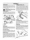
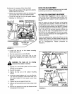
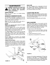
IELIEFVALVE
hydrostatic relief valve is provided so the unit can be
noved without the engine running. The lever which
Iperates the relief valve is located on the console. See
igure 9.
o operate the relief valve, place the hydrostatic con-
rol lever in neutral, release the parking brake, push
he lever forward and to the right to lock. Be certain to
elease the lever by pushing it to the left before operat-
ng the engine.
NDICATOR LIGHTS (Optional)
f your unit is equipped with indicator lights, two or
:hree indicator lights are located in the dash panel. If a
ight illuminates when attempting to start the unit, pro-
_'eedas follows.
3LUTCH--Depress the clutch pedal.
PTO--Place lift lever in the BLADES OFF position.
OIL (Vanguard Engines Only)--Check the crankcase
3il level, and add oil as required.
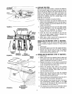
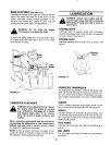
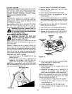
CUTTINGCONTROLS
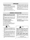
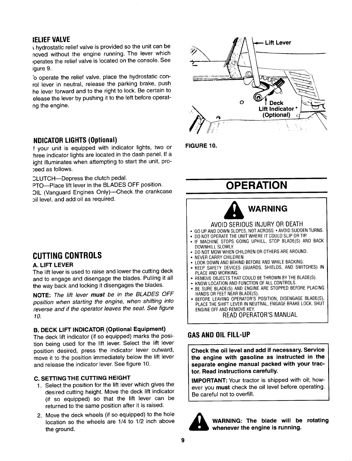
A. LIFT LEVER
The lift lever is used to raise and lower the cutting deck
and to engage and disengage the blades. Pulling it all
the way back and locking it disengages the blades.
NOTE: The rift lever must be in the BLADES OFF
position when starting the engine, when shifting into
reverse and if the operator leaves the seat. See figure
10.
Lift Lever
O
Lift Indicator °
FIGURE 10.
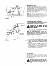
OPERATION
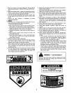
WARNING
AVOID SERIOUS INJURY OR DEATH
• GOUPANDDOWNSLOPES,NOTACROSS.•AVOIDSUDDENTURNS.
• DONOTOPERATETHEUNITWHEREIT COULDSLIPORTIP.
• IF MACHINE STOPS GOING UPHILL, STOP BLADE(S) AND BACK
DOWNHILL SLOWLY.
• DONOTMOWWHENCHILDRENOROTHERSAREAROUND•
• NEVERCARRY CHILDREN.
• LOOKDOWNANDBEHINDBEFOREAND WHILE BACKING.
• KEEP SAFETY DEVICES (GUARDS, SHIELDS, AND SWITCHES) IN
PLACEAND WORKING.
• REMOVEOBJECTSTHATCOULDBETHROWNBYTHE BLADE(S).
• KNOWLOCATIONAND FUNCTIONOFALL CONTROLS•
• BESURE BLADE(S)AND ENGINEARESTOPPEDBEFOREPLACING
HANDSORFEETNEARBLADE(S).
• BEFORELEAVING OPERATOR'SPOSITION, DISENGAGEBLADE(S),
PLACETHE SHIFTLEVERIN NEUTRAL,ENGAGEBRAKELOCK,SHUT
ENGINEOFFAND REMOVEKEY.
READ OPERATOR'S MANUAL
B. DECK LIFT INDICATOR (Optional Equipment)
The deck lift indicator (if so equipped) marks the posi-
tion being used for the lift lever. Select the lift lever
position desired, press the indicator lever outward,
move it to the position immediately below the liftlever
and release the indicator lever. See figure 10.
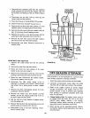
C. SETTING THE CUTTING HEIGHT
1. Select the position for the liftlever which gives the
desired cutting height. Move the deck liftindicator
(if so equipped) so that the lift lever can be
returned to the same positionafter itis raised.
2. Move the deck wheels (if so equipped) to the hole
location so the wheels are 1/4 to 1/2 inch above
the ground.
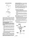
GAS AND OIL FILL-UP
Check the oil level and add if necessary. Service
the engine with gasoline as instructed in the
separate engine manual packed with your trac-
tor. Read instructions carefully.
IMPORTANT: Your tractor is shipped with oil; how-
ever you must check the oil level before operating.
Be careful not to overfill.
WARNING: The blade will be
rotating
whenever the engine is running,