


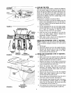

Ifadjustmentisnecessary,followthesesteps:
1. Raisebothrearwheelsoffthegroundby placing
blocksundertherearframe.
2. Removethetransmissionpanelbyremovingthe
parkingbrakeknobandtrussmachinescrews.
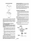
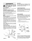
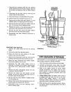
3. Loosenthe hexjam nuton the speedselector
adjustingrod.Seefigure11.
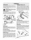
Hex Nut
Scissor Speed Selector
Bracket Adjusting Rod
Scissor
Mounting
Bracket
Hex Jam Nut
(Loosen)
DECKLEVELINGADJUSTMENT
If an uneven cut is obtained, the deck may be leveled
by following instructions in Assembly section.
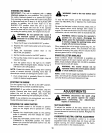
CUTTING DECKENGAGEMENTADJUSTMENT
The cutting deck engagement may be adjusted to
make certain deck is disengaged when lift lever is in
the BLADES OFF position. Correct adjustment as
follows.
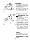
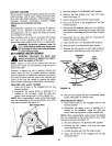
With the engine off, place the lift lever in the highest
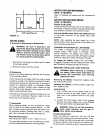
cutting position (first position). Remove the cotter pin
and flat washer which secure the disengagement rod
to the stabilizer shaft assembly. See figure 12. Shorten
the rod by threading it in until the ferrule is against the
back of the slot in the lift shaft assembly, and the rod
lines up with the hole in the stabilizer shaft. For more
belt tension the disengagement rod must be length-
ened. To decrease belt tension the disengagement rod
must be shortened.
Check the adjustment by placing the lift lever in the
BLADES OFF position. The deck should move up and
forward, allowing the belt to become loose. Start and
test for disengagement. Repeat procedure as
necessary.
FIGURE 11.
4. Loosen the hex nut on the scissor mounting
bracket. See figure 11.
5. Start the engine and run at full throttle.
6. Move the hydrostatic control lever until you find
neutral (rear wheels do not rotate in either direc-
tion).
,_ WARNING: The blade will be rotating
whenever the engine is running.
7. DeprEss the clutch-brake pedal until the scissor
brackets come together.
8. Shut off the engine.
9. Tighten the hex nut on the scissor mounting
bracket.
10. Thread the speed selector rod in or out of the fer-
rule until the hydrostatic control lever lines up in
the neutral position on the speed control index
bracket.
11. Tighten hex jam nut against the ferrule.
12. Replace the transmission panel and parking brake
knob.
13. Remove the blocks from under the frame and test
the operation of the tractor.
11
Stabilizer Shaft Disengagement Rod
Assembly
FlatWasher I 36" and
Hairpin Clip 138" Decks
Stabilizer Shaft Disengagement Rod
Assembly
Stabilizer Plate
Flat Washer 42" and
Hairpin Clip 46" Decks
FIGURE 12.