


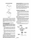

,ckHanger _-_
L
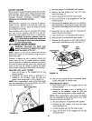
"IGURE 4.
ustable/
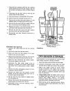
Positive Terminal
(Inside Rubber Boot)
il U
Q
/
Negative
Cable Negative Battery
FIGURE 5. Terminal Compartment
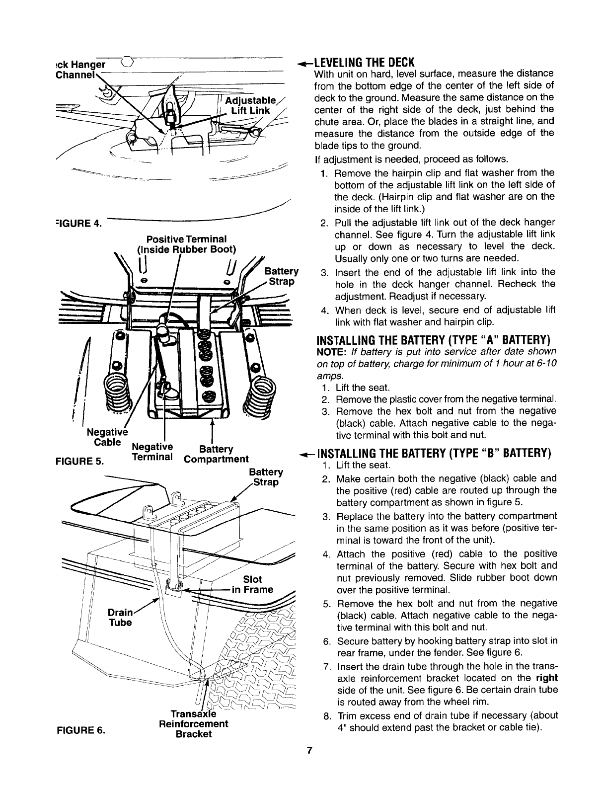
Battery
Battery
Reinforcement
FIGURE 6. Bracket
Slot
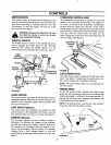
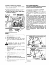
<--LEVELING THE DECK
With unit on hard, level surface, measure the distance
from the bottom edge of the center of the left side of
deck to the ground. Measure the same distance on the
center of the right side of the deck, just behind the
chute area. Or, place the blades in a straight line, and
measure the distance from the outside edge of the
blade tips to the ground.
If adjustment is needed, proceed as follows.
1. Remove the hairpin clip and flat washer from the
bottom of the adjustable lift link on the left side of
the deck. (Hairpin clip and flat washer are on the
inside of the lift link.)
2. Pull the adjustable lift link out of the deck hanger
channel. See figure 4. Turn the adjustable lift link
up or down as necessary to level the deck.
Usually only one or two turns are needed.
3. Insert the end of the adjustable lift link into the
hole in the deck hanger channel. Recheck the
adjustment. Readjust if necessary.
4. When deck is level, secure end of adjustable lift
link with flat washer and hairpin clip.
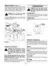
INSTALLING THE BATTERY(TYPE "A" BATTERY)
NOTE: If battery is put into service after date shown
on top of battery, charge for minimum of 1 hour at 6-10
amps.
1. Lift the seat.
2. Remove the plastic cover from the negative terminal.
3. Remove the hex bolt and nut from the negative
(black) cable. Attach negative cable to the nega-
tive terminal with this bolt and nut.
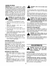
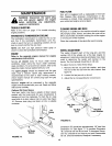
INSTALLING THE BATTERY(TYPE "B" BATTERY)
1. Lift the seat.
2. Make certain both the negative (black) cable and
the positive (red) cable are routed up through the
battery compartment as shown in figure 5.
3. Replace the battery into the battery compartment
in the same position as it was before (positive ter-
minal is toward the front of the unit).
4. Attach the positive (red) cable to the positive
terminal of the battery. Secure with hex bolt and
nut previously removed. Slide rubber boot down
over the positive terminal.
5. Remove the hex bolt and nut from the negative
(black) cable. Attach negative cable to the nega-
tive terminal with this bolt and nut.
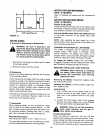
6. Secure battery by hooking battery strap into slot in
rear frame, under the fender. See figure 6.
7. Insert the drain tube through the hole in the trans-
axle reinforcement bracket located on the right
side of the unit. See figure 6. Be certain drain tube
is routed away from the wheel rim.
8. Trim excess end of drain tube if necessary (about
4" should extend past the bracket or cable tie).