


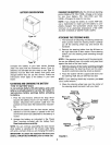
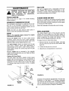


MAINTENANCE
WARNING: Disconnect the spark plug
wire and ground against the engine
before performing any adjustments,
repairs or maintenance.
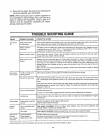
TROUBLE SHOOTING
Refer to the chart on page 17 for trouble shooting
engine problems.
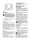
HYDROSTATICTRANSMISSION COOLING
The hydrostatic transmission is cooled by the oil, fan
and fins. If the hydrostatic transmission runs hot,
check to see if the fan is in operating condition, the oil
level is correct and the fins are clean.
NOTE: DO NOT use high pressure water spray or
steam to clean the hydrostatic transmission.
ENGINE
Refer to the separate engine manual for engine
maintenance instructions,
Service air cleaner every 10 hours under normal
conditions. Clean every few hours under extremely
dusty conditions. To service the air cleaner, refer to the
separate engine manual packed with your unit.
The spark plug(s) should be cleaned and the gap
reset once a season. Spark plug replacement is
recommended at the start of each mowing season;
check engine manual for correct plug type and gap
specifications.
Maintain engine oil as instructed in the separate
engine manual packed with your unit. Read and follow
instructions carefully.
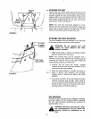
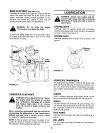
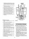
Optional Oil Drain Sleeve
Your lawn tractor may have a plastic oil drain sleeve
packed with the loose parts for your convenience in
draining oil from the crankcase. To drain the oil, snap
small end of oil drain sleeve onto oil sump. See figure
15. Remove drain plug and drain oil into a suitable
container.
Oil
,ump
FUELFILTER
Your unit is equipped with a replaceable in-line fuel
filter. Replace filter whenever contamination or dis-
coloration is noticed. Order replacement filter through
your authorized engine service dealer.
CLEANING ENGINE AND DECK
Any fuel or oil spilled on the machine should be wiped
off promptly. Grass, leaves, and other dirt must not be
left to accumulate around the cooling fins of the engine
or on any part of the machine.
Clean the underside of the deck after each mowing.
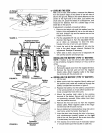
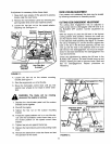
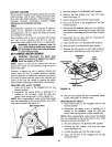
WHEEL ADJUSTMENT
The caster (forward slant of the king pin) and the
camber (tilt of the wheels out at the top) require no
adjustment. Automotive steering principles have been
used to determine the caster and camber on the
tractor. The front wheels should toe-in 1/8 inch.
To adjust the toe-in, follow these steps.
1. Remove the hex nut and lock washer, and drop
the end of the tie rod from the axle bracket. See
figure 16.
2. Loosen the hex jam nut on tie rod.
3. Adjust the tie rod assembly for correct toe-in.
Tie
Rod
\
Hex Jam,
Nut
Tie Rod
End
"ac'eil
Hex Nut
Lock Washer
/
FIGURE 16.
FIGURE 15.
Oil Drain
Sleeve
Dimension "B" should be approximately 1/8" less than
Dimension "A." See figure 17. To increase Dimension
"B," screw tie rod into tie rod end. To decrease Dimen-
sion "B," unscrew tie rod from tie rod end. Reassemble
tie rod. Check dimensions. Readjust if necessary.
13